Assembly
24
03.00 | GSM-W | Assembly and operating manual | en | 389108
5.3 Mounting the sensor
NOTE
Observe the assembly and operating manual of the sensor for
mounting and connecting.
The product is prepared for the use of sensors.
• For the exact type designations of suitable sensors, please see
catalog datasheet and
• For technical data for the suitable sensors, see assembly and
operating manual and catalog datasheet.
– The assembly and operating manual and catalog datasheet
are included in the scope of delivery for the sensors and are
available at schunk.com.
• Information on handling sensors is available at schunk.com or
from SCHUNK contact persons.
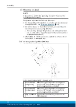
5.3.1 Assembly and setup of the MMS-P 22
Position and installation of the MMS-P magnetic switches
1 Sensor MMS-P
(left groove)
Monitoring gripper position 1 and gripper
position 2 in the left rotating angle end
position (signals SGL1 and SGL2)
2 Sensor MMS-P
(right groove)
Monitoring gripper position 1 and gripper
position 2 in the right rotating angle end
position (signals SGR1 and SGR2)
3 Stop for MMS-P Determining the clamping position of the
MMS-P sensor


