background image

Assembly 


20 

01.00| |en 


  •  Screw the power chuck onto the draw tube as far as it will go. 

(Make sure that the draw tube thread is flush.) 
The HSA 160,160/2, HSA-NZ 170/2,180/2, HSA 250, HSA 250/2 
and HSA 400 is screwed onto the draw bar using the screw 
(Item 15). (The screw must also be flush with the draw bar 
thread. 

  •  The chuck is screwed onto the intermediate flange (spindle)  

using the screws (Item 17). 
The run-out can be aligned as follows: Slightly loosen the 
screws (Item 17). Fit a dial gauge on the cylindrical surface of 
the chuck body (Item 1). Align the run-out using the set-screws 
(Item 23). Tighten the screws (Item 17) alternately. 

HSA 630/2:


  •  Lift the chuck with the flange screwed on (Item 10) in front of 

the spindle lug using an eye bolt until it is flush with the center 
of the spindle. The bore holes for the screws (Item 17) should 
be flush with the threaded holes in the spindle. 

  •  Screw onto the draw bar using the screw (Item 15). (The screw 

(Item 17) must also be flush with the draw rod thread.) 

  •  Slightly tighten the screws (Item 17) alternately. Also slightly 

tighten the screws (Item 19). 

  •  The run-out can be aligned as follows: Place a dial gauge on  

the cylindrical surface of the chuck body (Item 1). Adjust the 
set-screws (Item 23) to align the run-out. Securely tighten  
the screws (Item 17 and 19) alternately. 

Tighten the fastening screws, quality class 10.9, using a torque 
wrench.

 (See "Screw tightening torques" chapter 

(

 4, Page 15)

). 

On no account tighten the Allen key with an extension pipe or 
with hammer blows.


All HSA chuck types:


  •  Fit the guide bushing for the compensating clamping (Item 4)  

or self-centering clamping (Item 13) using the screws (Item 18). 

Summary of Contents for HSA 160

Page 1: ...0 88041389 HSA NZ 170 2 88027365 HSA 180 2 88036423 HSA 200 88002843 88002909 88002958 88004159 88018669 88020485 88026696 88028474 88028566 88039479 88039429 HSA 250 88018463 88018469 88019551 HSA 25...

Page 2: ...00 22 02 2016 en SCHUNK GmbH Co KG All rights reserved Dear customer congratulations on choosing a SCHUNK product By choosing SCHUNK you have opted for the highest precision top quality and best serv...

Page 3: ...14 2 8 2 jaw chuck 14 3 Warranty 15 4 Torques per screw 15 5 Scope of delivery 16 6 Technical data 17 6 1 Calculation of the clamping force based on the speed 17 6 2 Grades of Accuracy 18 6 3 Permissi...

Page 4: ...a third party these instructions must also be passed on Illustrations in this manual are provided for basic understanding of the product and may differ from the actual product design We accept no lia...

Page 5: ...ge WARNING Warning about hand injuries WARNING Warning about hot surfaces Applicable documents General terms of business Calculation of the jaw centrifugal forces Technology chapter in the lathe chuck...

Page 6: ...that the user has read and understood this operating manual in its entirety especially the chapter Basic safety notes The maximum RPM of the chuck and the required clamping force must be determined b...

Page 7: ...a power failure the chuck s clamping force may fail immediately and the workpiece may be released in an uncontrolled manner This poses a risk of death or injury to the operating personnel and can res...

Page 8: ...l from clothing or hair being caught on the chuck and being dragged into the machine Loose clothing or long hair may become caught on projecting parts of the chuck and be drawn into the machine The ma...

Page 9: ...ach between the jaws Wear safety gloves Observe the safety and accident prevention regulations during operation of the chuck especially in connection with machining centers and other technical equipme...

Page 10: ...n the machine spindle has come to a standstill If the clamping energy fails the workpiece must remain firmly clamped until the spindle is shut down and the workpiece is secured The technical safety re...

Page 11: ...pecial grease LINO MAX Unsuitable lubricants can have a negative impact on the functioning of the chuck clamping force coefficient of friction wear characteristics For product information about LINO M...

Page 12: ...failure if the servicing instructions for the chuck are disregarded The servicing instructions specified by the manufacturer must be complied with to ensure safe operation of the chuck Work must be c...

Page 13: ...2006 42 EC Personnel qualification Assembly and disassembly commissioning operation and repair of the chuck may be performed only by qualified specialists who have been instructed with respect to safe...

Page 14: ...n until the fault has been located and remedied Only allow specialists to remedy faults Spare parts Only ever use original SCHUNK spare parts Environmental regulations Comply with the applicable legal...

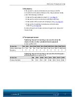
Page 15: ...tenance and lubrication intervals 9 Page 26 Parts touching the work piece and wearing parts are not part of the warranty Torques per screw Tightening torques for mounting screws used to clamp the chuc...

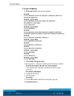
Page 16: ...039479 88039429 HSA 250 Id No 88018463 88018469 88019551 HSA 250 2 jaw chuck Id No 88028004 88034564 HSA 265 Id No 88003413 88003473 HSA 315 Id No 88037992 88040302 HSA 315 2 jaw chuck Id No 88029693...

Page 17: ...ion of the clamping force based on the speed S a F 0 00001096 M r K n2 Total clamping force Static clamping force Loss of centrifugal force The loss of centrifugal force must not exceed 50 of the stat...

Page 18: ...HSA 180 2 HSA 200 HSA 250 HSA 250 2 HSA 265 HSA 315 HSA 315 2 HSA 400 HSA 630 2 30 mm 30 mm 35 mm 35 mm 46 mm 46 mm 46 mm 46 mm 55 mm 55 mm 75 mm 100 mm Greater jaw distances after consultation with...

Page 19: ...ned inter mediate flange for radial and axial run out The permissible limit is 0 005 mm in accordance with DIN 6386 and ISO 3089 The contact surface must be chamfered and completely clean at the bore...

Page 20: ...g an eye bolt until it is flush with the center of the spindle The bore holes for the screws Item 17 should be flush with the threaded holes in the spindle Screw onto the draw bar using the screw Item...

Page 21: ...Assembly 01 00 en 21 Mounting the chuck Cylinder piston in foremost position R1 Push the chuck piston to its foremost position and measure with a depth gauge R2 R1 0 5 mm max 1 mm...

Page 22: ...djust to an eccentrically positioned workpiece within the specified limits see drawing The base jaws are therefore capable of compensating clamping with even pressure from all sides of the jaws of a w...

Page 23: ...The chuck can only be disassembled once it has been removed See HSA chuck assembly chapter 7 2 Page 19 WARNING Risk of injury due to the power chuck falling during transportation installation or remov...

Page 24: ...Unscrew the screws Item 29 from the chuck body Remove the guide strips Item 8 and 9 The base jaws Item 2 can now be removed Pull the guide part Item 5 with piston Item 3 out of the chuck body Item 1 P...

Page 25: ...ly use genuine SCHUNK spare parts when replacing damaged parts The chuck must be completely assembled including all the small components before start up Each small component may have a safety function...

Page 26: ...is applied clamping cylinder the base jaws must move evenly This method only provides a limited indication and does not replace measurement of the clamping force If the clamping force has dropped too...

Page 27: ...aping liquids and dispose of them properly in line with the statutory provisions Remove any identifiable plastic or aluminum parts installed in or on the chuck and dispose of them properly in line wit...

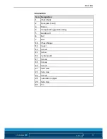
Page 28: ...80 2 HSA 200 HSA 250 HSA 265 HSA 315 HSA 315 2 HSA 400 and HSA 630 2 Item Designation 1 Chuck body 2 Base jaws 1 set 3 Piston 4 Compensating guide bushing 5 Guide part 6 Nut 7 Bolt 8 Screw 8 9 Guide s...

Page 29: ...ck body 2 Base jaws 1 set 3 Piston 4 Compensating guide bushing 5 Guide part 6 Nut 7 Bolt 10 Chuck flange 13 Cover 14 Screws 15 Screw 16 Center point 17 Screws 18 Screws 19 Screws 22 Set screw 23 Set...

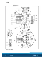
Page 30: ...Drawings 30 01 00 en Drawings HSA 315 without center point 12...

Page 31: ...Drawings 01 00 en 31 HSA 400 Compensation chuck with center point...

Page 32: ...Drawings 32 01 00 en HSA NZ 170 Compensation chuck...

Reviews: