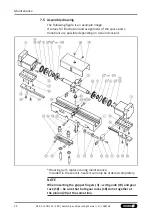
Assembly
Position "Gripper closed"
1. Set the gripper to position "Gripper closed".
2. Push proximity switch 1 in adjustable housing 1 and secure the
proximity switch with the slotted union nut.
3. Insert adjustable housing 1 (with proximity switch 1) into the
oblong hole of the bracket (3) and secure it with the counter
nut (4) so that a sensing distance of about 0.8 mm is present
between the clamping piece and the adjustable housing.
4. Push adjustable housing 1 as far as possible to the left.
5. Connect proximity switch 1.
6. Carefully push adjustable housing 1 in the oblong hole to the
right. If the proximity switch is attenuated, push the proximity
switch another 0.5 mm or so in the same direction.
7. Carefully tighten the counter nuts (4).
8. Open and close the gripper to test its functioning.
Position "Gripper open"
1. Set the gripper to position "Gripper open".
2. Push proximity switch 2 in adjustable housing 2 and secure the
proximity switch with the slotted union nut.
3. Insert adjustable housing 2 (with proximity switch 2) into the
oblong hole of the bracket (5) and secure it with the counter
nut (4) so that a sensing distance of about 0.8 mm is present
between the clamping piece and the adjustable housing.
4. Push adjustable housing 2 as far as possible to the right.
5. Connect proximity switch 2.
6. Carefully push adjustable housing 2 in the oblong hole to the
left. If the proximity switch is attenuated, push the proximity
switch another 0.5 mm or so in the same direction.
7. Carefully tighten the counter nuts (4).
8. Open and close the gripper to test its functioning.
Position "Part gripped" (O.D. gripping) by a stroke of at least 16
mm*
1. Set the gripper to position "Gripper open".
2. Push proximity switch 1 in adjustable housing 1 and secure the
proximity switch with the slotted union nut.
3. Push proximity switch 2 in adjustable housing 2 and secure the
proximity switch with the slotted union nut.
4. Insert adjustable housing 1 and 2 (with proximity switch) into
the oblong hole of the bracket (3) and secure it with the
counter nut (6) so that a sensing distance of about 0.8 mm is
present between the clamping piece (1) and the adjustable
housing.
5. Push adjustable housing 2 as far as possible to the right.
21
04.00 | KGG 220 - 280 | Assembly and Operating Manual | en | 389168

