Assembly
05.00|21151452 KSP plus-IN, KSP-LH plus-IN, KSP plus-IN2, KSP-LH plus-IN2 |en
23
the inductive proximity switches on the TANDEM clamping blocks.
The function for monitoring the jaw position can only be
connected externally. When joining, make sure the air feed-
throughs for the clamping system and the base plate are precisely
aligned.
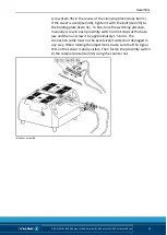
• Screw the two parts together using the four screws (item 19)
from the accessory pack. In doing so, observe tightening
torques.
• Remove the locking screws from the pneumatic connections on
the base plate.
• Connect the diaphragm pressure switch and set the switch to
the required minimum pressure.
Monitoring of the jaw position via inductive proximity
switches
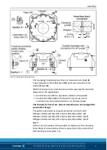
The TANDEM KSP-IN / KSP-LH-IN or KSP-IN2 / KSP-LH-IN2 clamping
system is prepared for use with INW 50 / INW 80 or IN S-M8-1 / IN
S-M8-2 inductive proximity switches for monitoring jaw positions.
The jaw stroke end positions for O.D. and I.D. clamping as well as
the exact clamping position can be monitored through recesses in
the base jaws of the clamping block. The signals can be directly
processed by the machine control system.
The monitoring result is: The clamping force block is open or
closed (for I.D. or O.D. clamping depending on the application)
• Information on handling sensors is available at schunk.com or
from SCHUNK contact persons.
• Technical data for the sensors can be found in the data sheets
(included in the scope of delivery or at schunk.com).
The proximity switch used has reverse polarity protection and is
short-circuit-proof.
For the proper use of the proximity switches, observe the
following:
• Protect the connection cables against hot chips and falling parts
by using a suitable metal hose or protection cover. For the IN2
version, merely protection against falling parts is required.
• Do not pull forcefully on the sensor cable.
• Do not subject the sensor cable to tensile strain.
• Install the sensor connection cable straight and do not twist it.
• Tighten the counter nut for clamping the sensor using a
suitable tool and moderate manual force.
• Do not exceed the permissible bending radius of the cable (
☞
catalog specifications)
5.5

