Maintenance and care
38
05.00|21151452 KSP plus-IN, KSP-LH plus-IN, KSP plus-IN2, KSP-LH plus-IN2 |en
Disassembling and assembling the clamping block
NOTE:
The base jaws (item 2), the chuck piston (item 3) and the housing
(item 1) are matched to each other. These parts cannot be
replaced individually. To replace these parts, ship the entire
clamping force block to SCHUNK along with a repair order.
When maintaining the clamping force block, first disassemble the
inductive proximity switches and if necessary the cover to avoid
damaging the sensitive connection cables.
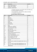
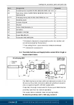
• Disassemble the connection cable to the pin terminal of the
inductive proximity switch on the separable elbow connector.
• Unscrew the screw (item 35).
• Remove the retainer plate (item 31) and if necessary the cover
with the inductive proximity switches (item 36) from the body
(item 1).
• Each inductive proximity switch is fastened with a hexagon nut
and washer (item 34).
The counter-supports (item 32) can be removed at the same
time as the proximity switches.
When replacing wearing parts (e.g. seals - for seal kit list see
) adhere to the following order:
1 Apply 6 bar of air pressure to the clamping system until the
jaws are in the OPEN position.
2 Remove the covering strip (item 7) and the guide strips (item
6).
3 Remove the cylindrical screw (item 14) from the chuck piston.
4 Remove the pressure line.
5 Pull the plugs (item 8) out of the housing (item 1).
6 Loosen the screws (items 9, 19) and remove the clamping
system from the base plate or machine table. Air may escape at
this point.
7 To remove the chuck piston (3)
for size 100, screw in one M10 x 25 screw in the center bore,
for size 160, screw one M12 x 25 screw in the center bore,
for size 250, screw two M6 x 25 screws in the lateral threaded
holes.
8 Pull the base jaws (item 2) out of the housing (item 1).
9 Before pulling off the cover (item 5), all the screws (item 21)
need to be removed. To take off the cover (5), screw two
7.1

