9
Montage- und Betriebsanleitung für
2-Finger-Parallelgreifer Type KTG
Assembly and Operating Manual for
2-Finger-Parallel-Gripper Type KTG
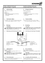
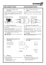
Montage und Einstellung der Näherungsschalter
1.
Lösen Sie die Klemmschraube an der Halterung.
2.
Schieben Sie die Näherungsschalter durch die Bohrungen in
der Halterung. Beachten Sie den Abstand von 0.5 mm zur
Schaltfahne.
3.
Sichern Sie die Näherungsschalter durch Anziehen der
Klemmschraube (Anzugsmoment max. 1 Nm).
4.
Stellen Sie gegebenenfalls die Schaltfahnen so ein, dass in
der von Ihnen gewünschten Stellung der Grundbacke sich
der Kopf der Schaltfahne über der Mitte des jeweiligen
Näherungsschalters befindet.
5.
Wenn Sie Zwischenstellungen abfragen wollen, müssen Sie
unter Umständen die lange Schaltfahne gegen die Schraube
M2 x 8 aus dem Beipack auswechseln. Sichern Sie die
Schaltfahne mit einem geeigneten Klebstoff.
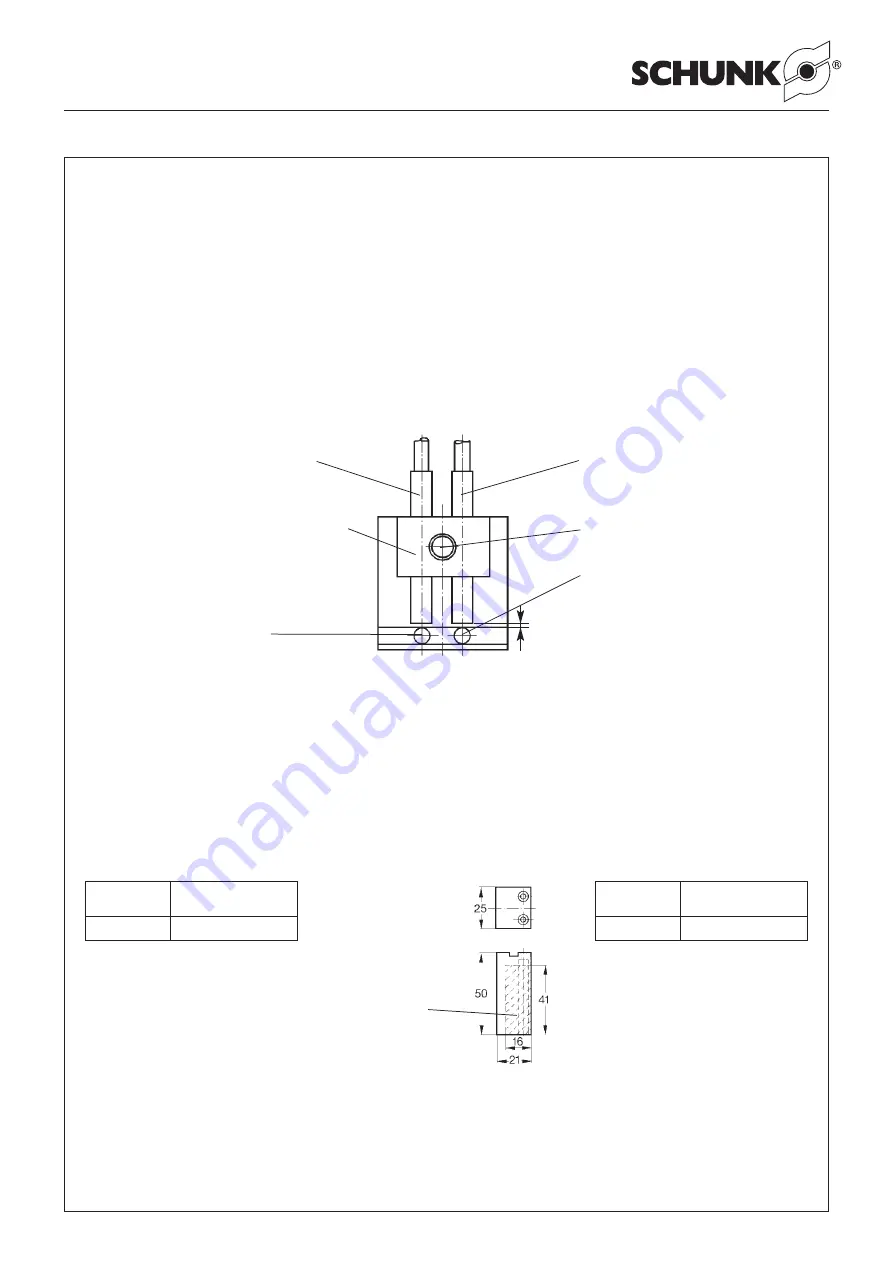
Näherungsschalter
»AUF«
Proximity switch
»open«
Klemmschraube
Clamping screw
kurze Schaltfahne
short switching cam
lange Schaltfahne
long switching cam
Bearbeitungsbereich für
spezifische Anpassung /
Machining area for special
adjustment works
0.5 mm
Halterung für Näherungsschalter
Bracket for proximity switch
Näherungsschalter
»ZU«
proximity switch
»closed«
11.2 Aufsatzbacken
Die Grundbacken sind mit je 4 Gewinden M3 und einem Steg
ausgestattet. Benutzen Sie mindestens 2 Gewinde zum
Befestigen Ihrer Aufsatzbacken.
ACHTUNG:
Max. Einschraubtiefe von 3 mm beachten!
Den Steg können Sie zum Fixieren der Aufsatzbacken ver-
wenden.
Backen-Rohlinge /
Blank:
–
zur direkten Befestigung auf Greifergrundbacken
–
werkstückspezifische Anpassung durch Bearbeitung der
Backen möglich
–
Geringes Gewicht durch Verwendung von hochfestem
Aluminium
Type
Ident-Nr. für 1 Satz
= 2 Stück
RB 50
300 280
Mounting and adjusting of proximity switches
1.
Loosen the clamping screw at the bracket.
2.
Move the proximity switch through the bore into the bracket.
Please make sure that the distance of 0.5 mm to the control
cam will be respected.
3.
Save the proximity switch by thightening the clamping screw
(tightening torque max. 1 Nm).
4.
In order to achieve the desired position of the base jaws, it
may be necessary to adjust the control cam in a way, that the
head of the control cam will be positionned in the middle of
the individual proximity switch.
5.
For sensoring of the intermediate positions, it may be neces-
sary to exchange the long control cam against the screw
M2 x 8 out of the accessories supplied. Secure the control
cam with an appropriate glue.
11.2 Top jaws
The base jaws are equipped with four each threads M3 and a
tongue. Always use at least 2 threads for fastening the top jaws.
CAUTION:
Please consider the max. thread reach of 3 mm!
The tongue may be used for fixing the top jaws.
Type
Id.-No. for 1 set
= 2 pcs.
RB 50
300 280
–
for direct fastening of the gripper base jaws
–
Adjustments to special workpieces at the jaws is possible
–
Low weight by using high-tensile aluminium
Wir arbeiten ständig an der Verbesserung unserer Produkte. Deshalb sind die veröffentlichten Abmessungen und Angaben unverbindlich.
We constantly try to improve our products. Therefore all drawings and information given are subject to chance.

