background image

Translation of the Original Manual

Assembly and Operation Manual
LDL 

Linear motor shaft

Summary of Contents for LDL-UL-0200

Page 1: ...Translation of the Original Manual Assembly and Operation Manual LDL Linear motor shaft...

Page 2: ...r the purpose of technical improvement Document number GAS341441 Version 06 00 29 09 2020 en SCHUNK Electronic Solutions GmbH All rights reserved Dear Customer thank you for trusting our products and...

Page 3: ...ransport 69 2 10 Malfunctions 70 2 11 Disposal 70 2 12 Warnings on the drive 70 2 13 Fundamental dangers 71 2 13 1 Protection during handling and assembly 71 2 13 2 Protection during commissioning and...

Page 4: ...he motor housing 100 7 3 1 Uninstalling the motor housing 101 7 3 2 Installing the motor housing 101 7 4 Changing the recirculating ball bearing 102 7 5 Changing the stroke measuring system 104 7 6 Ch...

Page 5: ...asic understanding and may differ from the actual product design In addition to these instructions the documents listed under Applicable documents 66 are applicable 1 1 1 Presentation of Warning Label...

Page 6: ...owing conditions Observe the applicable documents Applicable documents 66 Observe the ambient conditions and operating conditions Ambient conditions and operating conditions 68 Observe the maximum ser...

Page 7: ...manual 2 2 Reasonably foreseeable misuse The product is not suitable for the following applications Use as passenger or animal transportation Operation of the motor directly on the network Operation u...

Page 8: ...d the result may be serious injuries and significant property damage All work may only be performed by qualified personnel Before working with the product the personnel must have read and understood t...

Page 9: ...bly may impair the product s safety and cause serious injuries and considerable material damage Avoid any manner of working that may interfere with the function and operational safety of the product U...

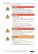
Page 10: ...ied Test the product after a malfunction to establish whether it still functions properly and no increased risks have arisen 2 11 Disposal Handling of disposal The incorrect handling of disposal may i...

Page 11: ...derable material damage Have all work carried out by appropriately qualified personnel For all work secure the product against accidental operation Observe the relevant accident prevention rules Use s...

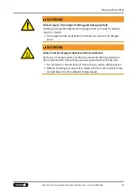
Page 12: ...ffective it must be assumed that the drive movement is faulty with its action being dependent on the control unit and the current operating condition of the drive Perform maintenance work modification...

Page 13: ...diagram Check whether covers and protective devices are fitted to prevent contact with live components Do not touch the product s terminals when the power supply is switched on Possible electrostatic...

Page 14: ...ack on again Only qualified electricians my carry out electrical installation work Disconnect the converters from the power supply The intermediate circuit capacitors must be discharged Note the corre...

Page 15: ...danger zone WARNING Risk of burns through contact with hot surfaces Surfaces of components can heat up severely during operation Skin contact with hot surfaces causes severe burns to the skin For all...

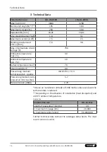
Page 16: ...temperature min C 10 Surfacetemperaturemax 70 Impermeability IP 00 Pressurising medium compressed air quality ISO 8573 1 7 4 4 Pressurising medium com pressed air min max bar 5 7 Noise emission dB A 7...

Page 17: ...types LDL UL 0200 and LDL US 0100 linear motor axes All versions of the linear motor axes are available with multiple slides Linear motor axes type LDL US 2 with two slides 77 06 00 LDL Assembly and...

Page 18: ...524 LxBV 111A 0122 LD L U S 0100 1 300 524 LxBV 111A 0122 Linear Motor Axis Profile type U supported S standard slide L long slide Size number of active slides Useful stroke Axis length V brake valve...

Page 19: ...le static load Permissible static load of the unit Item LDL US 0100 LDL UL 0200 Mx max Nm 406 406 My max Nm 340 657 Mz max Nm 340 657 Fy max N 6350 6350 Fz max N 6350 6350 79 06 00 LDL Assembly and Op...

Page 20: ...tuated when the axis is at a standstill Forced movement when the holding brake is activated will damage it Do no move the axis without the brake having been released Ensure that the pneumatic holding...

Page 21: ...respect The shock absorbers are designed as emergency shock absorbers and are intended to protect the axis from being destroyed in the event of an operating error or malfunction Optional shock absorbe...

Page 22: ...ansport and storage 5 1 Transport The product is a precision device The packaging must protect the product from all external effects such as mechanical shocks and humidity 5 2 Storage Store the produc...

Page 23: ...and secure against being switched back on again Only qualified electricians my carry out electrical installation work Disconnect the converters from the power supply The intermediate circuit capacitor...

Page 24: ...enness of the mounting surface Dimensions in mm Edge length Permissible unevenness 100 0 02 100 0 05 Assembly The unit can be screwed both to the end plates and or to the slide and fixed with a center...

Page 25: ...Assembly 6 1 1 dimensions LDN Ex xxxx A H G L1 L2 LDL US 0100 180 104 52 224 112 LDL UL 0200 280 205 85 324 162 85 06 00 LDL Assembly and Operation Manual en GAS341441...

Page 26: ...y out electrical installation work Disconnect the converters from the power supply The intermediate circuit capacitors must be discharged Note the correct sequence for connecting cables first the grou...

Page 27: ...6 2 1 PE ground M5 grounding screw 6 2 2 Electrical connections at the slide Connections on the product 1 Power connector 2 Measuring system connection 87 06 00 LDL Assembly and Operation Manual en G...

Page 28: ...escription LE100 M12 Operating voltage VDC 5 5 Output signal Sin Cos Signal amplitude Vss 1 10 Offset sine cosine V 2 5 0 5 Signal period m 1000 Reference signal periodic mm 20 Distance reading head s...

Page 29: ...amplitude Vss 1 10 Offset sine cosine V 2 5 0 5 Signal period m 1000 Reference signal periodic mm 20 Distance reading head measuring tape mm 0 05 0 2 Pin Assignment 1 N C 2 SIN 3 SIN 4 GND 5 COS 6 CO...

Page 30: ...en GAS341441 6 2 5 MSA111C DQ absolute measuring system Description MSA111C DQ Operating voltage VDC 10 30 Distance reading head magnetic tape mm 0 05 0 2 Pin Configuration 1 Vcc 2 Tsens 3 GND 4 TXN 5...

Page 31: ...Output signal Hiperface sin cos Signal amplitude Vss 1 10 Offset sine cosine V 2 5 0 5 Signal period m 1000 Distance between reading head and measuring tape mm 0 1 0 2 Pin Assignment 1 SIN 2 SIN 3 CO...

Page 32: ...ng system Description MSA111C Operating voltage VDC 4 5 30 Output signal SSI Sin Cos Signal amplitude Vss 1 10 Offset sine cosine V 2 5 0 5 Signal period m 1000 Distance reading head measuring tape mm...

Page 33: ...power connector Pin Assignment Note 1 U Phase drive controller 2 PE Protective conductor drive controller 3 W Phase drive controller 4 V Phase drive controller A n c B n c C Temperature D Temperature...

Page 34: ...en GAS341441 6 3 Pneumatic connection only for the holding brake CAUTION Observe the requirements for the air supply Technical Data 76 Pneumatic connection Switching valve 1 Manual actuation 2 Compre...

Page 35: ...Assembly Pneumatic diagram Pneumatic diagram for holding brake 95 06 00 LDL Assembly and Operation Manual en GAS341441...

Page 36: ...rmanent magnets Medical devices such as pacemakers or hearing aids may be destroyed or cause malfunctions Keep a sufficient minimum distance to the secondary part if you have a pacemaker or are wearin...

Page 37: ...system that is ready to operate Only carry out maintenance work which is described in this document or for person who have been trained and authorized NOTE The maintenance work can either be carried...

Page 38: ...ble for damage Shut down the machine system in the event of defects and replace the cables weekly Rub the guide strips 1 with an oil soaked cloth Every 2 to 4 weeks Clean secondary part 2 Every 5 000...

Page 39: ...and repair work 7 2 Overview Overview linear motor axes 1 End plate 2 Guide block 3 Motor housing 4 Motor connector 5 Guide blade carrier 6 Measuring system 99 06 00 LDL Assembly and Operation Manual...

Page 40: ...fting screws WARNING Danger of crushing Motors and steel parts are attracted by the secondary part Do not place motors and metal parts in the vicinity of the secondary part WARNING Risk of burns throu...

Page 41: ...force 4 Completely remove the motor housing 3 7 3 2 Installing the motor housing 1 Fit the lifting screws 2 Let them protrude 5 mm 2 Place the motor housing 3 on the guide rail 3 Slowly unscrew the l...

Page 42: ...ual en GAS341441 7 4 Changing the recirculating ball bearing Uninstalling the recirculating ball bearing Uninstalling the recirculating ball bearing 1 Uninstallingthemotorhousing Uninstallingthemotorh...

Page 43: ...lide from the side 3 Tighten the screws to some extent 2 4 Screw in the assembly tool 8 to pre load the recirculating ball bearing to 300N while carefully moving the guided slide back and forth by han...

Page 44: ...nd Operation Manual en GAS341441 7 5 Changing the stroke measuring system CAUTION Due to the adjustment work required the stroke measuring system should only be changed by specialist personnel 7 6 Cha...

Page 45: ...the guide rail 5 using a knife point and pull it off 4 Carefully clean the guide rail 5 of all adhesive residue using petroleum ether 5 Place the magnetic strip 3 onto the guide rail 5 6 Length of th...

Page 46: ...d when the compressed air supply is switched on and this can lead to dangerous movements The slide or guide rail must not be moved when the brakes are applied This can damage the product This especial...

Page 47: ...talling the disk springs 4 make sure the individual disk springs are placed in the correct position Short slides are equipped with 5 disk springs Long slides with double brakes are each equipped with...

Page 48: ...hanical limit switches and inductive reference switch 1 Unscrew the mounting screws 1 of the switch baseplate 2 2 Unscrew the mounting screws 3 of the switch 4 and 5 and replace the switch 3 Install t...

Page 49: ...ve action Attachments on the product have too much mass Check cycle time calculation Specifications made by control unit are not correct Correct specifications Error in the drive controller See docume...

Page 50: ...riginal spare parts of SCHUNK when replacing spare and wear parts 9 2 Wearing parts The expected life span depends on the respective application ambient conditions load and cycle time The information...

Page 51: ...rails 2 H 12 all Profile guide 1 H 13 a all End plate 2 GAS 319 743 14 a LDL US 0100 Motor MGL US 0100 1 GAS 368 645 14 b LDL UL 0200 Motor MGL UL 0200 1 GAS 368 659 14 c LDL US 0100 Motor MGL US 0100...

Page 52: ...GAS341441 9 4 Measuring system Item Designation Num ber Op tion Order Number 41a Reading head LE100 5 m 1 GAS 336 025 41b Reading head LE100 10 m 1 GAS 341 782 42 Magnetic strip LE100 1 H GAS 346 611...

Page 53: ...Spare parts 9 5 Holding brake Item Designation Quantity Order Number 1 Holding brake 1 GAS 361 490 113 06 00 LDL Assembly and Operation Manual en GAS341441...

Page 54: ...1 GAS 312 263 63 Sto d mpfer 2 GAS 319 701 9 7 Aids Item Designation Quantity Order Number 1 Cleaning cloth 1 GAS 372 063 2 Oil 50 ccm 1 GAS 301 478 3 Measuring system tester 1 GAS 323 712 4 Documenta...

Page 55: ...chinery Directive 2006 42 EC is confirmed Applied harmonized standards especially EN ISO 12100 2010 Safety of machinery General principles for design Risk assessment and risk reduction EN 60204 1 2006...

Page 56: ...ration X 1 1 3 Materials and products X 1 1 4 Lighting X 1 1 5 Design of machinery to facilitate its handling X 1 1 6 Ergonomics X 1 1 7 Operating positions X 1 1 8 Seating X 1 2 Control Systems 1 2 1...

Page 57: ...rements for protective devices X 1 5 Risks due to other hazards 1 5 1 Electricity supply X 1 5 2 Static electricity X 1 5 3 Energy supply other than electricity X 1 5 4 Errors of fitting X 1 5 5 Extre...

Page 58: ...fety requirements for certain categories of machinery X 2 1 Foodstuffs machinery and machinery for cosmetics or pharmaceutical products X 2 2 Portable hand held and or guided machinery X 2 2 1 Portabl...

Page 59: ......

Page 60: ...Folgen Sie uns I Follow us 09 2020 2020 SCHUNK GmbH Co KG 06 00 LDL Montage und Betriebsanleitung de en GAS341441...

Reviews: