background image

Assembly

03.00 | MEG 50 EC | Assembly and Operating Manual | en | 389201

21

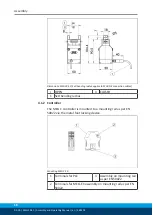
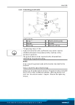
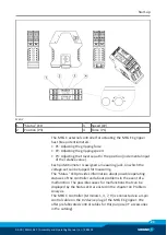
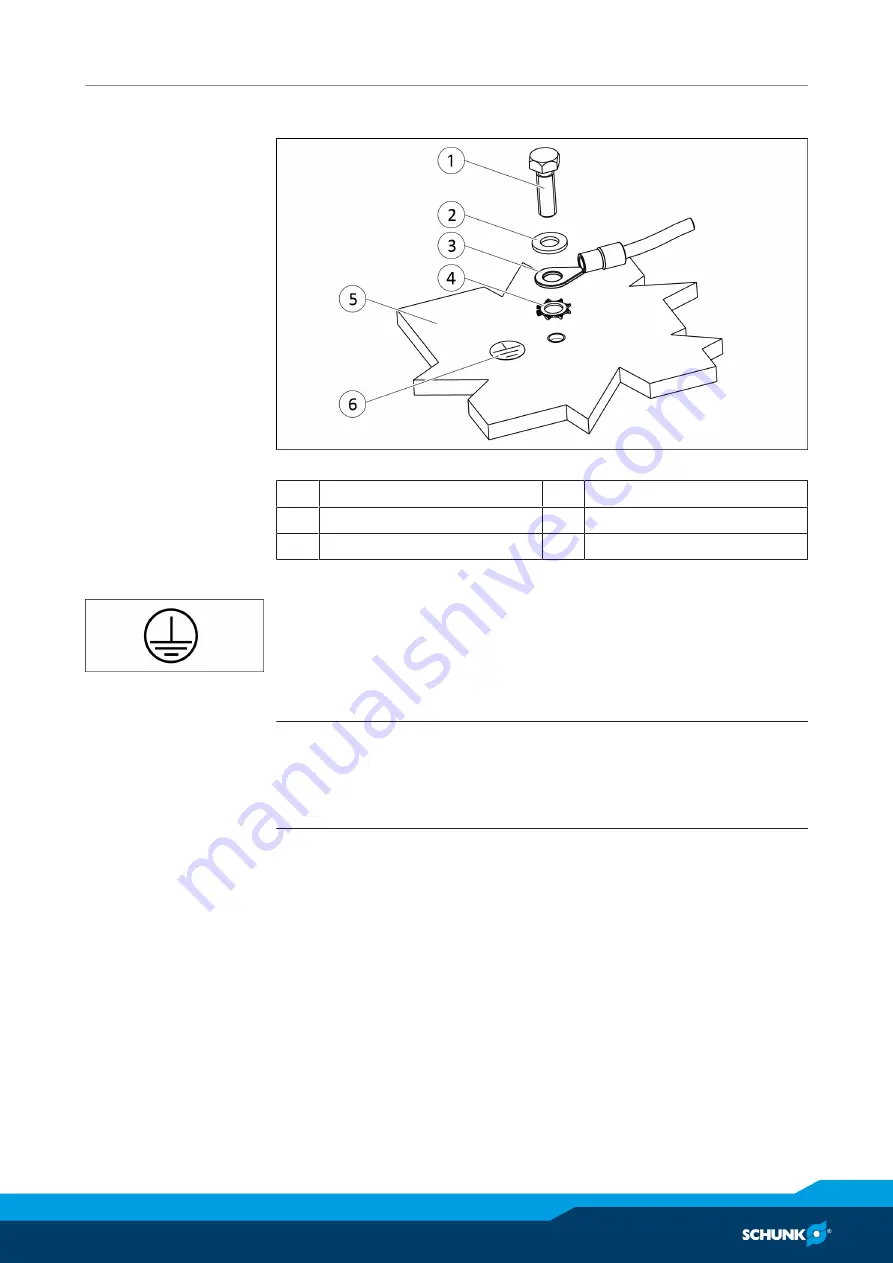
4.2.3 Connecting ground cable

Ground connection

1

Screw *

4

Toothed lock washer

2

Washer

5

Product

3

Cable lug

6

Ground marking

*) Tightening torque: 5 Nm
A ground connection with a sufficient cross-section must be
established between the product and the machine on the
customer's premises. 
The ground cable must be mounted on the threaded hole
identified by the ground marking.

NOTE

Only connect the ground cable at the location intended for this
purpose.
Always mount the ground cable singly.

Always use all components to screw in the ground cable and install
them in this order: toothed lock washer, cable lug, washer and
bolt. See "Ground connection" diagram. Observe the tightening
torque.

Summary of Contents for MEG 40 EC

Page 1: ...Translation of original operating manual Assembly and Operating Manual MEG 50 EC Electrical parallel gripper ...

Page 2: ...terations for the purpose of technical improvement Document number 389201 Version 03 00 05 02 2020 en SCHUNK GmbH Co KG All rights reserved Dear Customer thank you for trusting our products and our family owned company the leading technology supplier of robots and production machines Our team is always available to answer any questions on this product and other solutions Ask us questions and chall...

Page 3: ...ons 8 2 7 Personnel qualification 8 2 8 Personal protective equipment 9 2 9 Notes on safe operation 9 2 10 Transport 10 2 11 Malfunctions 10 2 12 Disposal 10 2 13 Fundamental dangers 11 2 13 1 Protection during handling and assembly 11 2 13 2 Protection during commissioning and operation 11 2 13 3 Protection against dangerous movements 12 2 13 4 Protection against electric shock 13 2 14 Notes on p...

Page 4: ...tion 28 5 7 2 Step specification 30 5 7 3 Gripping force specification 32 5 8 Example of a possible gripping cycle 33 5 9 Table of functions 35 6 Troubleshooting 37 6 1 Status LED flashing 37 6 2 Product does not execute a complete stroke 38 6 3 The gripping force drops 38 6 4 Product opens or closes jerkily 38 7 Maintenance 39 7 1 Maintenance intervals 39 7 2 Lubricate gripper 40 7 3 Disassembly ...

Page 5: ...his manual Illustrations in this manual are provided for basic understanding and may differ from the actual product design In addition to these instructions the documents listed under Applicable documents 6 are applicable 1 1 1 Presentation of Warning Labels To make risks clear the following signal words and symbols are used for safety notes DANGER Danger for persons Non observance will inevitably...

Page 6: ... the specified maintenance and lubrication intervals Observe the ambient conditions and operating conditions Parts touching the workpiece and wear parts are not included in the warranty 1 3 Accessories A wide range of accessories are available for this product For information regarding which accessory articles can be used with the corresponding product variants see catalog data sheet 1 4 Scope of ...

Page 7: ...ed for industrial and industry oriented use Appropriate use of the product includes compliance with all instructions in this manual 2 2 Not intended use It is not intended use if the product is used for example as a pressing tool stamping tool lifting gear guide for tools cutting tool clamping device or a drilling tool Any utilization that exceeds or differs from the appropriate use is regarded as...

Page 8: ... application parameters Technical data 16 Make sure that the product is a sufficient size for the application Make sure that the environment is free from splash water and vapors as well as from abrasion or processing dust Exceptions are products that are designed especially for contaminated environments 2 7 Personnel qualification Inadequate qualifications of the personnel If the personnel working...

Page 9: ...r the required personal protective equipment Observe the valid safety and accident prevention regulations Wear protective gloves to guard against sharp edges and corners or rough surfaces Wear heat resistant protective gloves when handling hot surfaces Wear protective gloves and safety goggles when handling hazardous substances Wear close fitting protective clothing and also wear long hair in a ha...

Page 10: ...havior in case of malfunctions Immediately remove the product from operation and report the malfunction to the responsible departments persons Order appropriately trained personnel to rectify the malfunction Do not recommission the product until the malfunction has been rectified Test the product after a malfunction to establish whether it still functions properly and no increased risks have arise...

Page 11: ...r the product s safety and cause serious injuries and considerable material damage Have all work carried out by appropriately qualified personnel For all work secure the product against accidental operation Observe the relevant accident prevention rules Use suitable assembly and transport equipment and take precautions to prevent jamming and crushing Incorrect lifting of loads Falling loads may ca...

Page 12: ...e effective it must be assumed that the drive movement is faulty with its action being dependent on the control unit and the current operating condition of the drive Perform maintenance work modifications and attachments outside the danger zone defined by the movement range To avoid accidents and or material damage human access to the movement range of the machine must be restricted Limit prevent ...

Page 13: ...ched to all electrical components according to the wiring diagram Check whether covers and protective devices are fitted to prevent contact with live components Do not touch the product s terminals when the power supply is switched on Possible electrostatic energy Components or assembly groups may become electrostatically charged When the electrostatic charge is touched the discharge may trigger a...

Page 14: ...th Stand clear of suspended loads and do not step within their swiveling range Never move loads without supervision Do not leave suspended loads unattended Wear suitable protective equipment WARNING Risk of injury from objects falling and being ejected Falling and ejected objects during operation can lead to serious injury or death Take appropriate protective measures to secure the danger zone WAR...

Page 15: ...able protective equipment WARNING Risk of burns through contact with hot surfaces Surfaces of components can heat up severely during operation Skin contact with hot surfaces causes severe burns to the skin For all work in the vicinity of hot surfaces wear safety gloves Before carrying out any work make sure that all surfaces have cooled down to the ambient temperature WARNING Risk of injury from o...

Page 16: ...ical sum of the individual forces acting on the gripper jaws at a distance of P 25 mm Values for friction coefficient µ 0 1 and safety factor v 2 The values can be increased in the case of form fitting Distribution of the mechanical end positions after 100 consecutive strokes A controller is needed to operate the gripper For this purpose SCHUNK offers the MEG C 50 ID number 307005 More technical d...

Page 17: ...ction 4 1 1 Gripper Connection dimensions MEG 50 EC 1 for centering 8 0 1 for M5 thread 3 for bore hole 8 0 1 for M5 thread 2 Centering Ø8 2x 4 Centering 8 4x The gripper is mounted to the base or side via M5 threads The centering is performed via the centering sleeves contained in the accessory kit ...

Page 18: ...UNK connection cables I OPEN II CLOSED 1 5xD bending radius 4 1 2 Controller The MEG C controller is mounted to a mounting rail as per EN 50022 via the metal foot locking device Mounting MEG C 50 1 Terminals for PLC 3 Assembly on mounting rail as per EN 50022 2 Terminals for MEG EC assembly on mounting rail as per EN 50022 ...

Page 19: ...Assembly 03 00 MEG 50 EC Assembly and Operating Manual en 389201 19 Dimensions MEG C 50 4 2 Electrical connection 4 2 1 Gripper connector assignment X2 device plug on the MEG 40 EC ...

Page 20: ...osition output GND analog output 7 Connection 1 motor Connection for MEG 50 EC Brown 8 9 Connection 2 motor Connection for MEG 50 EC White 10 Supply 24 V 24 VDC 2 11 External reset Digital input 12 Supply GND GND 13 Gripper stopped Digital output 14 Reference run carried out Digital output 15 Analog position output 0 5V Analog output 16 24V PLC 24 VDC 10 17 GND PLC GND potential of PLC 18 Target p...

Page 21: ...st be established between the product and the machine on the customer s premises The ground cable must be mounted on the threaded hole identified by the ground marking NOTE Only connect the ground cable at the location intended for this purpose Always mount the ground cable singly Always use all components to screw in the ground cable and install them in this order toothed lock washer cable lug wa...

Page 22: ...the output Target pos reached Prepositioning reached output issues high signal The gripper is prepositioned in positioning movement mode then the workpiece is gripped in live movement The gripper can be prepositioned accordingly and the gripping cycle can start anew 5 2 MEG 50 EC and MEG C 50 connection description The MEG 50 EC does one stroke of 8 mm per jaw Stroke force and speed can be set on ...

Page 23: ...ch potentiometer is assigned a measuring jack on which the voltage set can be tapped for measuring The Status LED provides information about possible operating statuses of the controller and about problems in the event of a malfunction The possible causes for malfunctions that can be displayed by the Status LED are listed in the chapter on Problem Analysis The MEG C controller terminals 1 3 7 9 is...

Page 24: ...d with a falling edge During command execution it must be ensured that the input signal does not bounce The gripper opens if a rising edge is identified at the Gripper open input In the event of a falling edge the command is ended and the gripper stops This works in the same way for the Gripper closed input It is necessary to end the previous command with a falling edge before a new command is exe...

Page 25: ...on of the Gripper open or Gripper closed command If the gripper moves to an end position or onto a workpiece in position mode the current movement command is reset and the gripper stops The superordinate control unit only receives the digital signal Gripper stopped terminal 13 but not the Target position reached signal terminal 18 MEG 50 EC achieves a relative positioning accuracy of 0 1 mm This i...

Page 26: ...s specified a Low signal is again issued at the output The output Analog position output terminal 15 issues the current gripper position in the form of an analog value after each reference run and at any point in time The following diagram shows in which way the output voltage and the position of the gripper are connected Analog position output Output voltage in V Position in mm Connection between...

Page 27: ...mentally in the application 5 5 Live mode In order to safely grip a workpiece it is recommendable to perform the gripping procedure in live movement mode Procedure Ø The voltage at the input Analog steps terminal 23 and at the Pos potentiometer potentiometer P3 must be set to 0V Ø The analog values for speed Analog input Speed terminal 22 or potentiometer Speed potentiometer P2 and force Analog in...

Page 28: ... the gripper control potentiometer there must not be any voltage on the external analog inputs put inputs onto GND if possible If the analog voltages are specified by the PLC it is recommendable that the internal analog voltages are set to 0 V on the potentiometers You can also combine external via PLC and internal via the potentiometers specifications If for instance the position movement is to b...

Page 29: ...lue to the superordinate control The diagrams below show the connection between the speed and the input voltage of the external input Speed terminal 22 or the Speed potentiometer potentiometer P2 Power mode Speed f input voltage via external input Gripping speed in mm s Input voltage of external input in V Speed in live mode in relation to external analog input Speed terminal 22 Power mode Speed f...

Page 30: ...ep position mode in relation to input voltage on the Speed potentiometer potentiometer P2 5 7 2 Step specification As described in Section Position mode Position mode the distance the gripper is to cover from the current position towards open or closed is to be specified by Analog input Position terminal 23 or by Pos potentiometer potentiometer P3 This means that the stroke that the gripper perfor...

Page 31: ...hen the voltage is specified via the Pos potentiometer potentiometer P3 on the controller MEG C Travel preset f input voltage via external input Travel in mm y 0 7613x 0 1186 Input voltage in V relative traverse path when the analog voltage is specified on terminal 23 Travel preset f input voltage on potentiometer y 1 5995x 0 1792 Travel in mm Input voltage in V relative traverse path when the ana...

Page 32: ... show the relationship between the gripping force and the input voltage of the external input Force terminal 24 or the Force potentiometer potentiometer P1 for finger length P 25 mm Gripping force preset f input voltage via external input Input voltage in V Travel in mm Gripping force when the analog voltage is specified on terminal 24 Gripping force preset f input voltage via potentiometer Force ...

Page 33: ...ched output terminal 18 and at the digital output Gripper stopped terminal 13 Now the specification for the stroke Analog input Position terminal 23 or on the Pos potentiometer potentiometer P3 is set to zero Volt so as to switch from the position mode to the live mode The live movement is started via the Gripper open or Gripper closed command The set value for the gripping force can be changed du...

Page 34: ...ured via the output analog position output Ø After successful performance of a positioning movement a High signal is issued at the Target pos reached output terminal 18 and at the digital output Gripper stopped terminal 13 Ø The voltage at the input Analog steps terminal 23 and at the Pos potentiometer potentiometer P3 must be set to 0V Ø The analog values for speed Analog input Speed terminal 22 ...

Page 35: ... 14 Reference run carried out 0V not carried out 24V carried out 15 Analog position output 0V 5 V approximately current position 0V inside 5V outside 18 Target position reached 0V target position not reached 24V target position reached 19 Reference run 0V standstill 24V execute command with gripper open or closed 20 Gripper closed 0V standstill 24V execute command 21 Gripper open 0V standstill 24V...

Page 36: ... open number of steps L L 0V 10V extern 0V 5V Poti 0V 10V extern 0V 5V Poti 0V 10V extern 0V 5V Poti L Gripper closed number of steps L L 0V 10V extern 0V 5V Poti 0V 10V extern 0V 5V Poti 0V 10V extern 0V 5V Poti L Gripper open live mode L L 0V 10V extern 0V 5V Poti 0V extern 0V Poti 0V 10V extern 0V 5V Poti L Gripper closed live mode L L 0V 10V extern 0V 5V Poti 0V extern 0V Poti 0V 10V extern 0V...

Page 37: ...e Check connection of the gripper to the controller and correct if necessary Check the coil resistances of the motor cables to each other approx 8 2 Ohm LED on controller flashes continuously approx once every 2 sec Excessive temperature on the controller Lower gripping force set value Provide sufficient cooling for controller LED on controller flashes continuously approx once every 4 sec Under or...

Page 38: ... a SCHUNK repair order or dismantle product 6 3 The gripping force drops Possible cause Corrective action Too much grease in the mechanical movement space Clean and lubricate product Maintenance 39 6 4 Product opens or closes jerkily Possible cause Corrective action Too little grease in the mechanical guiding areas Clean and lubricate product Maintenance 39 Mounting surface is not sufficiently fla...

Page 39: ...ient and application conditions shortened maintenance cycles can ensure the lifespan is maintained CAUTION Material damage due to hardening lubricants Lubricants harden more quickly at temperatures above 60 C leading to possible product damage Reduce the lubricant intervals accordingly CAUTION Damage to property caused by insufficient lubrication Continuously traveling short strokes when the produ...

Page 40: ...the greasing areas Ø Move the gripper to the closed position and lubricate the greasing areas Ø Move the gripper to the open position and lubricate the greasing areas Ø Fully open and close the gripper several times 7 3 Disassembly and assembling This product must not be disassembled for maintenance CAUTION Material damage due to improper disassembly Incorrect works can cause damage to the mechani...

Page 41: ...allel gripper MEG 50 EC electric and controller MEG 50 EC C ID number 0306010 0307005 The partly completed machine may not be put into operation until conformity of the machine into which the partly completed machine is to be installed with the provisions of the Machinery Directive 2006 42 EC is confirmed Applied harmonized standards especially EN ISO 12100 2010 Safety of machinery General princip...

Page 42: ...for the overall machine Fulfilled for the scope of the partly completed machine Not relevant 1 1 Essential Requirements 1 1 1 Definitions X 1 1 2 Principles of safety integration X 1 1 3 Materials and products X 1 1 4 Lighting X 1 1 5 Design of machinery to facilitate its handling X 1 1 6 Ergonomics X 1 1 7 Operating positions X 1 1 8 Seating X 1 2 Control Systems 1 2 1 Safety and reliability of c...

Page 43: ...Risks of uncontrolled movements X 1 4 Required characteristics of guards and protective devices 1 4 1 General requirements X 1 4 2 Special requirements for guards X 1 4 2 1 Fixed guards X 1 4 2 2 Interlocking movable guards X 1 4 2 3 Adjustable guards restricting access X 1 4 3 Special requirements for protective devices X 1 5 Risks due to other hazards 1 5 1 Electricity supply X 1 5 2 Static elec...

Page 44: ...ation from Annex 1 is to be supplemented from here forward 2 Supplementary essential health and safety requirements for certain categories of machinery X 2 1 Foodstuffs machinery and machinery for cosmetics or pharmaceutical products X 2 2 Portable hand held and or guided machinery X 2 2 1 Portable fixing and other impact machinery X 2 3 Machinery for working wood and material with similar physica...

Reviews: