Assembly
26
02.00|NSL3 turn 450-3, 450-3-Z, 570-5, 570-5-Z |en
For optimum machining results, the clamping station must be
operated in dynamic operation with a turbo pulse activated at the
turbo connection so as to achieve the highest pull down forces.
Failure to observe this fact may result in relative movement
between the clamping station and the clamping pallet/workpiece.
The clamping station may only be put into dynamic operation
when the turbo pulse at the turbo connection is activated.
Visual pressure indicator for turbo monitoring
The clamping station is equipped with a pressure indicator for
visually monitoring the operating modes. An
indicator pin
on the
built-in pressure display indicates the operating condition of the
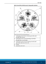
VERO-S quick-change pallet modules (see Fig. "Connections of the
clamping station"
). When the clamping system is
pressurized with compressed air via the unlocking connection, all
of the clamping modules are unlocked. The
indicator pin
on the
pressure display drops to the »unlock« operating condition.
Clamping pallets, devices or workpieces can now be inserted in or
removed from the unlocked modules of the clamping station.
After uncoupling the air supply from the unlocking connection, the
indicator pin
remains down and the clamping modules close via
the spring-actuated locking procedure. If the air supply is attached
to the turbo connection, the pull down force of the clamping
modules increases. The »turbo function« operating status is
indicated by the extended
indicator pin
. The indicator pin on the
pressure display always remains in the most recently selected
operating mode. A switch symbol on the pressure display is used
to monitor the current operating mode.
Description and functions of the clamping points
The clamping station NSL3 turn is available in two designs.
4.3.3
4.4

