background image

Sensors

12 Sensors

The quick-change pallet system NSR maxi 220 is prepared for using
the inductive stroke measuring system and the inductive proximity
switch NI 32 (see chapter "Coupling Interface" 

}

 6.4 [

/

 25]

).

• Information on handling sensors is available at schunk.com or

from SCHUNK contact persons.

• Technical data for the sensors can be found in the data sheets

(included in the scope of delivery or at schunk.com).

The proximity switch used has reverse polarity protection and is
short-circuit-proof.
For the proper use of the proximity switches, observe the
following:
• Do not pull on the cable of the sensor.
• Do not dangle the sensor from the cable.
• Do not excessively tighten the mounting screw or clips.
• Do not exceed the permissible bending radius of the cable (

catalog specifications).

• Prevent proximity switch from coming into contact with hard

objects or with chemicals; in particular, nitric, chromic or
sulfuric acid.

Proximity switches are electronic components which can react
sensitively to high-frequency interference or electromagnetic
fields.
• Check that the cable is correctly connected and installed. There

must be sufficient distance between the switches and sources
of interference and their supply cables.

• Parallel switching of multiple sensor outputs of the same design

(npn, pnp) is permissible, though this does not increase the
permissible load current.

• Please note that the leakage current of the individual sensors is

accumulative (by about 2 mA).

43

09.00 | NSR maxi 220 / PKL maxi 220 | VERO-S robot coupling for pallet
handling | en | 0489051

Summary of Contents for NSR maxi 220

Page 1: ...Translation of Original Operating Manual VERO S robot coupling for pallet handling NSR maxi 220 PKL maxi 220 Translation of Assembly and Operating Manual ...

Page 2: ...51 Version 09 00 29 11 2022 en Dear Customer Thank you for trusting our products and our family owned company the leading technology supplier of robots and production machines Our team is always available to answer any questions on this product and other solutions Ask us questions and challenge us We will find a solution Best regards Your SCHUNK team Customer Management Tel 49 7572 7614 1300 Fax 4...

Page 3: ...neral Installation Notes 19 6 3 Mounting and Connection 20 6 3 1 Unlocking Connection 22 6 3 2 Turbo Connection 23 6 3 3 Air Purge Connection with Cleaning Function 23 6 3 4 Pneumatic Circuit Diagram 24 6 4 Coupling Interface 25 6 4 1 PKL maxi 220 Pallet Coupling 26 6 5 Tolerances and Installation Conditions for SPA 80 30RF Clamping Pins in Customer specific Pallet Coupling 29 6 6 Application Exam...

Page 4: ...terial 39 10 3 Proximity Switches and Supply Cables for Single or Replacement Orders 40 11 Assembly drawings 41 12 Sensors 43 13 Appendix 46 14 Translation of the original declaration of incorporation 48 4 09 00 NSR maxi 220 PKL maxi 220 VERO S robot coupling for pallet handling en 0489051 ...

Page 5: ... this manual are provided for basic understanding of the product and may differ from the actual product design We accept no liability for damage resulting from the failure to observe and comply with this operating manual 1 1 Warnings To make risks clear the following signal words and symbols are used for safety notes DANGER Dangers for persons Non observance will inevitably cause irreversible inju...

Page 6: ...arning about hand injuries WARNING Warning about hot surfaces 1 2 Applicable documents General terms of business Catalog data sheet of the purchased product Data sheet positioning system PMI14V F166 2E2 0 35M V15 Y in appendix 13 46 The documents labeled with an asterisk can be downloaded from schunk com ...

Page 7: ...echnical data 5 16 The product is intended for industrial and industry oriented use Appropriate use of the product includes compliance with all instructions in this manual 2 2 Not intended use The VERO S robot coupling for pallet handling is not being used as intended if for example It is used as load handling or lifting equipment It is used for turning applications without consulting SCHUNK It is...

Page 8: ...e During operation erroneous or negligent loosening of the clamping pin must be prevented using suitable countermeasures disconnecting the power supply after locking use of check valves or safety switches Check the screw fitting of the clamping pin on the pallet coupling at regular intervals to ensure that it is secure In pallet handling setup mode only one operator may generally work on the robot...

Page 9: ...pping or falling if the operational environment is not clean e g contaminated with cooling lubricants or oil Ensure that the working environment is clean before starting assembly and installation work Wear suitable safety boots Follow the safety and accident prevention regulations when operating the robot coupling especially when working with machine tools and other technical equipment CAUTION Ris...

Page 10: ...In the event of eccentricity on the coupling interfaces the relevant traveling axes of the handling system must be adjusted The robot coupling must lie flush with the pallet coupling with no tilt angle and eccentricity when joining A rigid handling system must be used with high loading weights For the automated coupling process it is advisable to use the air purge to clean the coupling interface T...

Page 11: ... be performed by qualified personnel Before working with the product the personnel must have read and understood the complete assembly and operating manual Observe the national safety regulations and rules and general safety instructions The following personal qualifications are necessary for the various activities related to the product Trained electrician Due to their technical training knowledg...

Page 12: ...mounted must be stopped immediately and remain shut down until the malfunction has been located and remedied Only allow specialists to remedy malfunctions Spare parts Only use original SCHUNK spare parts Environmental regulations The applicable environmental regulations must be observed for all maintenance and repair work 2 7 Personal protective equipment Use of personal protective equipment Perso...

Page 13: ... applicable documents 1 2 6 Observe the ambient conditions and operating conditions Observe the maximum number of clamping cycles 5 16 Observance of the specified care and maintenance instructions 7 33 Parts touching the workpiece and wear parts are not included in the warranty 13 09 00 NSR maxi 220 PKL maxi 220 VERO S robot coupling for pallet handling en 0489051 ...

Page 14: ...9 x 1 5 4 elbow screw in unions G1 8 1 sensor connection cable to inductive stroke measuring system 1 sensor BES 516 324 EO C S49 00 3 NI 32 1 angular plug with supply line suitable for NI 32 4 1 Accessories Accessories see catalog or data sheets when ordering separately PKL maxi 220 pallet coupling Clamping pin SPA 80 30RF Pneumatic screw connections Teaching device ID 9988354 for inductive posit...

Page 15: ...essed air quality according to ISO 8573 1 7 4 4 Inductive position measuring system For monitoring the clamping slide position OPENED CLAMPED mounted on the perimeter of the quick change pallet system OPENED position and CLAMPED position are preset Range of measurement 14 mm Voltage 18 30 V DC Output 2 x PNP closer Protection class IP 67 Housing Zinc die cast nickel plated Active surface PBT Conne...

Page 16: ...leration forces that have to be taken into consideration for the transport load To operate the robot coupling with dynamic handling it is essential for the maximum acceleration of the machine to be known The acceleration has an effect even in the case of an abrupt deceleration e g when the emergency stop switch is actuated Inclusion of the acceleration values is of crucial importance for the opera...

Page 17: ...maxi 220 M 4000 Nm Result of calculation Taking into account the robot acceleration the loading weight obtained in the calculation example is permissible A higher loading weight requires a shortening of the effective lever length from the coupling interface to the center of gravity of the load or a reduction in the robot acceleration For every change to the technical data a calculation must be per...

Page 18: ...only be carried out by specialist personnel Disconnect the energy supply lines and ensure that there is no residual energy in the system when performing assembly modification maintenance or adjustment work The hoses and cables required for the energy supply for the robot coupling must be laid and protected suitably on the pallet handling Wear protective equipment protective gloves and safety shoes...

Page 19: ...amping units are mounted make sure that the flatness and height deviation of the locating surfaces from module to module based on a 200 mm gage for bore holes lies within 0 02 mm NOTE When connecting the quick change pallet systems ensure that it is only possible to completely ventilate the piston chamber via the air connections during the locking process The relevant valves or shut off valves sho...

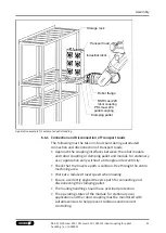
Page 20: ...gned as a fitting screw for precise alignment Precise alignment and positioning of the quick change pallet system requires that the fitting bores Ø 14 H7 on the opposite side are precisely positioned in the mounting position The inductive position measuring system is completely installed on the quick change pallet system and preset for monitoring the OPENED and CLAMPED positions NOTE Detaching thr...

Page 21: ...d absorption of torques Turbo connection via G1 8 fitting Air purge connection with cleaning function G1 8 Locating surfaces for pallet coupling Fastening connection for M12 cylindrical screw M14 x 20 detaching threads Torque pin via fitted bushings Inductive position measuring system for monitoring OPENED CLAMPED Fastening hole for M12 Ø 14f7 fitting screw M14 x 20 detaching threads Clearance for...

Page 22: ...wings 11 41 item 28 for sealing the bottom hose free direct connections When the turbo connection is used the spring actuated locking procedure is actively supported with air pressure If the turbo connection is not used the relevant side of the piston must be able to ventilate To operate the robot coupling the support of the turbo function is generally recommended 6 3 1 Unlocking Connection If com...

Page 23: ... housing cover for the clamping system This connection can be used for example to blow out the coupling interface or to also monitor the presence of the clamping pallet using a differential pressure switch For interface cleaning the NSR maxi 220 has two air connections at the side for the blow out or cleaning function using a G1 8 connection thread The positively driven air flow is released on the...

Page 24: ... Turbo connection 6 bar Blow out air 2 bar 6 bar Optional air purge contact monitoring max 2 bar 15 l min or blow out air 2 bar 6 bar volume flow 30 l min Compressed air supply Flow control valve Pressure gauge Pressure switch 3 2 directional control valve 5 3 directional control valve center position ventilated Pneumatic circuit symbols 15 l min upon air purge Air purge contact monitoring with 2 ...

Page 25: ... The pallet coupling engages in the fitted bushings of the robot module using alignment pins during joining Control function for presence of pallet coupling via inductive proximity switch NI 32 Torque pin variant I Pallet coupling PKL maxi 220 ID No 0471950 Clamping pallet Air ducts for cleaning function Torque pin variant I Position orientation and torque support through self centering mold incli...

Page 26: ...L maxi 220 Pallet Coupling The PKL maxi 220 pallet coupling ID no 0471950 was designed as a pallet changing interface for the NSR maxi 220 robot coupling play when joining with the robot module The pallet coupling provides the connection to the clamping pallet The interface of the pallet coupling has two cylindrical pins for position orientation as well as four mounting screws for adapting the cla...

Page 27: ...e Centering slants for torque pin version I Depth of engagement Lag screw for installing the clamping pallet always observe depth of engagement Cylindrical pin for position orientation Contact surface of clamping pallet PKL maxi 220 pallet coupling 27 09 00 NSR maxi 220 PKL maxi 220 VERO S robot coupling for pallet handling en 0489051 ...

Page 28: ...ed to retain support height Observe tightening torque of screw DIN EN ISO 4762 M24 12 9 1 x Fitting length Pallet not included in scope of delivery of PKL maxi 220 PKL maxi 220 pallet coupling for bore hole Gap without edge chamfer lengthwise to mounting surface Connection interface between the clamping pallet and pallet coupling The height of the clamping pallet must be at least 40 mm ...

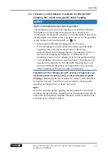
Page 29: ...sufficiently thick mounting material in the adapter strip for the pallet coupling The installation dimensions see illustration Tolerances and Installation Conditions for SPA 80 30RF clamping pins are based on different adapter strip materials for the customer pallet coupling and must be always be observed Installation of the clamping pin with incorrect components e g excessively short mounting scr...

Page 30: ...A 80 30RF clamping pins Tolerances and installation conditions for installation in a customer specific pallet coupling ID No A B C D E F G H SPA 80 30RF 0471181 28 35 M30 36 48 M24 30 35 6 6 Application Example for Automated Pallet Loading The NSR maxi 220 clamping system was designed for automated pallet loading The robot coupling with the handling system is the interface between the machine work...

Page 31: ...ng pallet and module for stationary use application early without a tilt angle and eccentricity Check that the traverse path is collision free through the entire machining area Work at a reduced travel speed when loading Ensure a correctly aligned traverse path for connecting and disconnecting the clamping pallet The loading handling should have overload protection The operating states of the modu...

Page 32: ...mple Positioning when loading 4x clamping pins on the change pallet for the quick change pallet systems of the clamping station 1 x centering taper Robot flange Industrial robot Quick change clamping station Robot coupling in unlocked coupling process Connect blast air cleaning function during loading NSR maxi 220 robot coupling PKL maxi 220 pallet coupling Connect or release the clamping pallet A...

Page 33: ...nit The robot coupling is ready for use with non lubricated compressed air Make sure that the contact surfaces of the interface are always clean Make absolutely sure that no chips of any kind can enter the interface and that the interface does not fill with cooling emulsion which is particularly possible with vertical positioning of the clamping pin axis If the interface should fill with cooling e...

Page 34: ...e leaks in the clamping system test the entire pneumatic system e g with Metaflux leak detection spray If any leaks are identified check the seals and replace them if necessary Leaks at the plug in connections or in the pneumatic lines for example must be sealed and defective components replaced Every 100 000 clamping cycles the screw connections between the robot coupling and the robot flange and...

Page 35: ...oximity switch not switching Check the proximity switch on the sensor head and on the connection cable for damage replace proximity switch if necessary Cable plug in connection to the supply cable Check the plug in connections tighten if necessary Replace type IN proximity switch or separately available supply cable Proximity switch moves independently Tighten the hexagonal nut for clamping Replac...

Page 36: ...pallet coupling with reference pin ID 0471950 complete and a separate teaching device must be used for this NOTE The teaching device and the pallet coupling are not included in the scope of delivery for the robot coupling NSR maxi 220 Please note S1 position of reference pin CLAMPED with turbo S2 position OPENED General information The teach in process for the two switching windows is done via a s...

Page 37: ... then goes back to its normal operating mode The LEDs of the teaching device now respond according to the switching state of the respective output An unsuccessful teach in process e g in the case of a teach in attempt beyond the range of measurement is indicated by the LED flashing rapidly 16 Hz for 1 5 s The previous switching limits are kept By pressing the key for 6 5 sec the sensor can be rese...

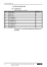
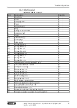
Page 38: ...t List NSR maxi 220 ID no 0471942 Item Designation Quantity 5 Cylindrical pin 2 11 Cover cap 8 12 Slide washer 1 19 O ring Ø 104 x 3 1 21 O ring Ø 148 x 3 1 22 O ring Ø 31 x 3 1 23 O ring Ø 32 x 1 5 4 25 O ring Ø 22 x 2 5 1 26 O ring Ø 156 x 2 1 27 O ring Ø 21 x 1 1 28 O ring Ø 9 x 1 5 4 Wearing parts we recommend replacing when maintenance is performed ...

Page 39: ... 1 26 O ring Ø 156 x 2 1 27 O ring Ø 21 x 1 1 28 O ring Ø 9 x 1 5 4 30 Screw DIN EN ISO 4762 M12 x 85 10 9 7 32 Screw DIN 7984 M6 x 30 8 8 4 33 Compression spring 10 35 Set screw M4 x 4 1 36 Set screw M8 x 8 1 38 Set screw M6 x 6 10 41 G1 8 locking screw 4 42 Set screw M8 x 1 x 6 1 43 G1 8 elbow screw in union 4 50 Inductive position measuring system 1 51 Screw DIN EN ISO 4762 M8 x 35 1 52 Screw D...

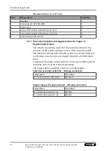
Page 40: ...tch for the control function for the presence of the pallet coupling consists of the sensor type BES 516 324 EO C S49 00 3 NI 32 with a short connection cable and round plug connection plus an angular plug with a W M8 supply cable If required the single components for the two part INW inductive proximity switch can be ordered separately The supply cable is available in two connecting lengths Induc...

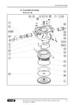
Page 41: ...Assembly drawings 11 Assembly drawings NSR maxi 220 41 09 00 NSR maxi 220 PKL maxi 220 VERO S robot coupling for pallet handling en 0489051 ...

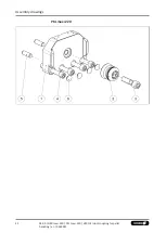
Page 42: ...Assembly drawings 42 09 00 NSR maxi 220 PKL maxi 220 VERO S robot coupling for pallet handling en 0489051 PKL maxi 220 ...

Page 43: ... the mounting screw or clips Do not exceed the permissible bending radius of the cable catalog specifications Prevent proximity switch from coming into contact with hard objects or with chemicals in particular nitric chromic or sulfuric acid Proximity switches are electronic components which can react sensitively to high frequency interference or electromagnetic fields Check that the cable is corr...

Page 44: ... Angular plug with supply line WK 5 M8 plug connection 5 meter cable length individual ID 0301502 Size M8 x 1 x 45 mm Switching function PNP closer Switching distance 1 5 mm Voltage 10 30 V DC Ripple 10 Max current on contact 200 mA short circuit proof Switching hysteresis 15 of the nominal switching distance Temperature range 40 C to 85 C Switching frequency approx 5000 Hz Voltage drop max load 2...

Page 45: ...e pallet coupling see chapter Coupling Interface 6 4 25 The connection cable must not be excessively twisted and certainly not damaged When making the adjustment make sure that the signal LED on the sensor is easily visible Carry out a function check by alternately inserting and withdrawing the clamping pallet in the change interface Then fasten the proximity switch using the lock nut for the sens...

Page 46: ...Appendix 46 09 00 NSR maxi 220 PKL maxi 220 VERO S robot coupling for pallet handling en 0489051 13 Appendix ...

Page 47: ...Appendix 47 09 00 NSR maxi 220 PKL maxi 220 VERO S robot coupling for pallet handling en 0489051 ...

Page 48: ...ay not be put into operation until conformity of the machine into which the partly completed machine is to be installed with the provisions of the Machinery Directive 2006 42 EC is confirmed Applied harmonized standards especially EN ISO 12100 2010 Safety of machinery General principles for design Risk assessment and risk reduction EN ISO 4414 2010 Pneumatic fluid power General rules and safety re...

Page 49: ......

Page 50: ......

Page 51: ......

Page 52: ...Spanntechnik KG Lothringer Str 23 D 88512 Mengen Tel 49 7572 7614 0 Fax 49 7572 7614 1099 info de schunk com schunk com Folgen Sie uns I Follow us 11 2022 2022 SCHUNK GmbH Co KG 09 00 NSR maxi 220 PKL maxi 220 VERO S robot coupling for pallet handling en 0489051 ...

Reviews: