5
Montage- und Betriebsanleitung
für Schwenkeinheit Type OSE 40
Assembly and Operating Manual for
for Swivel Unit Type OSE 40
3.
Lieferumfang
(Positionsnummern, siehe Ersatzteilstücklisten Kapitel 10, sowie
Schnittdarstellungen Kapitel 11)
– Schwenkeinheit
(ohne Adapterplatte und ohne Näherungsschalter)
– 2 O-Ringe für bodenseitigen Direktanschluss
(Baustein C: 3 Stück) Pos. 51
– 2 Pass-Schrauben Pos. 76 oder Pos. 77
– 2 Zentrierbuchsen Pos. 20
– 2 Drosselrückschlagventile (Baustein C: 3 Stück) Pos. 97 und
Pos. 98 (im Beipack)
– 1 Halterung Pos. 21 incl. 2 Näherungsschalterhülsen Pos. 32,
Näherungsschalterhalter Pos. 22
– 2 Schaltnocken (Baustein C: 3 Stück) Pos. 23
– 1 Steckschlüssel (bei Baustein B) Pos. 39
Einheiten mit Luftdurchführung
– 4 O-Ringe Pos. 52
ZUBEHÖR: (bei separater Bestellung, siehe Katalog)
– Näherungsschalter
– Sicherheitsventil
4.
Technische Daten
(siehe Katalog)
HINWEIS:
Bitte prüfen Sie, ob Ihr Einsatzfall anhand des Berechnungs-
programms Auswahlsystem für SCHUNK Schwenkeinheiten
geprüft wurde.
Falls nicht, kann für die Stoßdämpfer keine Gewährleistung über-
nommen werden.
Der von den Einheiten ausgehende Luftschall ist
≤
70 dB (A).
3.
Scope of Delivery
(item-no., see spare part lists chapter 10, as well as the
sectional view chapter 11).
– Swivel unit
(without adaptor plate and without proximity switch)
– 2 O-rings for direct connection at the bottom
(module C: 3 pieces) item 51
– 2 Dowel screws item 76 or item 77
– 2 centering bushings item 20
– 2 double check valves (module C: 3 pieces) item 97 and
item 98 (in the enclosed pack)
– 1 bracket item 21 incl. 2 sleeves for proximity switches
item 32, bracket for proximity switch item 22
– 2 control cams (module C: 3 pieces) item 23
– 1 actuation key (for module B) item 39
Units with an air through feeding system
– 4 O-rings item 52
ACCESSOIRES: (on separate order, see catalogue)
– Proximity switch
– Safety valve
4.
Technical Data
(see catalogue)
NOTE:
Please make sure that your case of application was checked with
our calculation programme “Selection System for SCHUNK
Swivel Units”.
If not, we can’t give warranty for the shock absorbers.
The airborne noise emitted is
≤
70 dB (A).
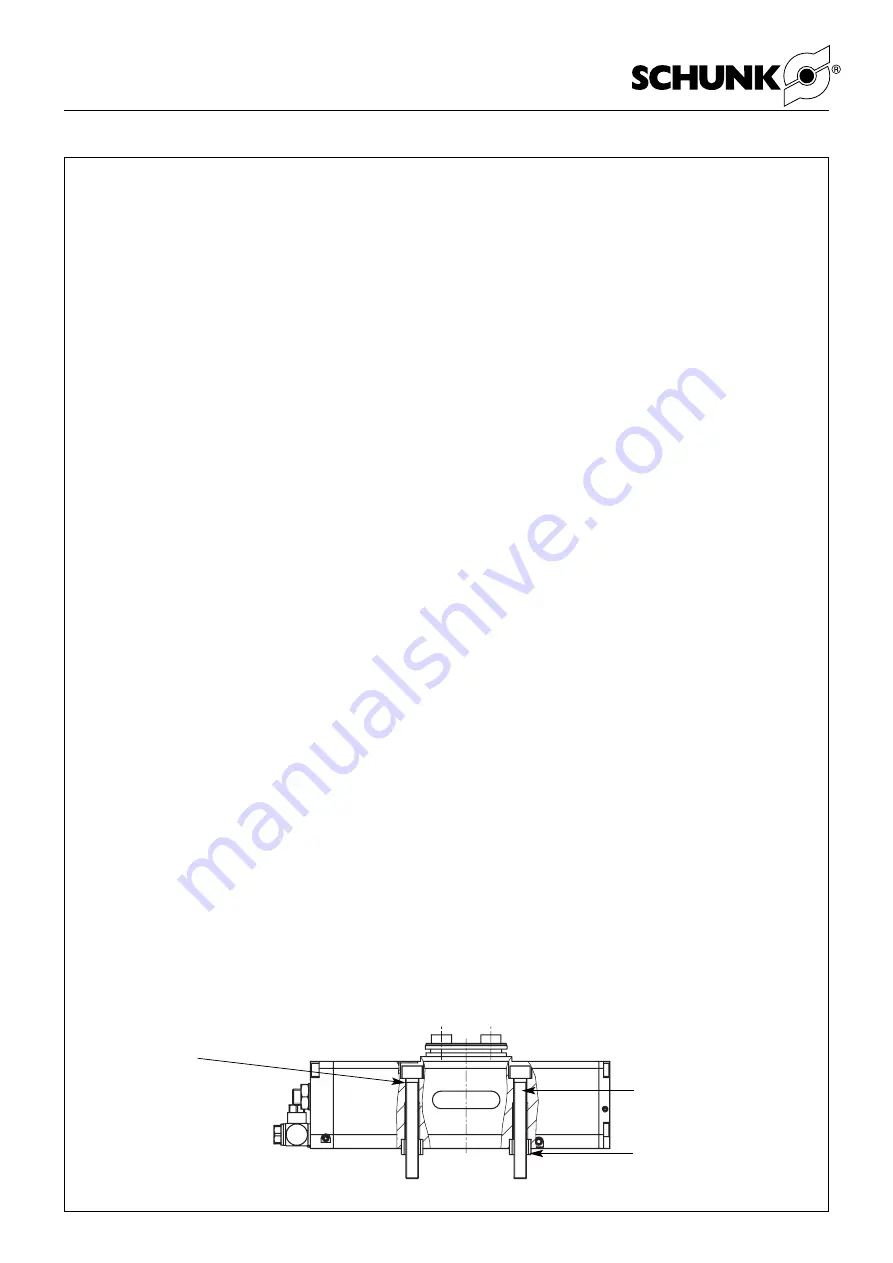
Durchgangsloch für
Schrauben (Pos./item 69):
M8 x 65 DIN 912
Through-hole for screws
(Pos./item 69)
M8 x 65 DIN 912
Innengewinde: M10
Internal thread: M10
Zentrierhülse / Centering sleeve
(Pos./item 20): Ø 14
f7
5.
Assembly
The swivel unit can be fastened with 2 socket head cap screws
M8 x 65 (item 69) or 2 internal threads.
To locate swivel unit use two centering sleeves (item 20) from the
enclosed pack.
5.
Montage
Die Schwenkeinheit kann an den 2 Innengewinden oder mit
Schrauben M8 x 65 (Pos. 69) befestigt werden.
Zur Zentrierung verwenden Sie die Zentrierhülsen (Pos. 20) aus
dem Beipack.


