background image

Maintenance

08.00 | PFH 150- 300 | Assembly and Operating Manual | en | 389270

33

6.4 Disassembly of the module

Position of the item numbers 

Assembly drawing

 [

}

 35]

Ø

Traverse the gripper to the completely open position.

Ø

Remove the compressed air hose.

Ø

Unscrew the threaded pins (29). You will thus release slightly
the tension of the rotary covers (20).

Ø

Unscrew the Screws (37 and 63).

Ø

Remove the upper covers (72 and 73).

 CAUTION

The rotary covers (20) can still be tensioned!

Carefully remove Screws (64) and final cover (71)

Ø

Remove the screws (64).

Ø

Remove the final cover (71).

Ø

Remove the reaming bolts (31).

Ø

Remove the rotary covers (20).

Ø

Remove the screws (62).

Ø

Remove the housing covers (6).

NOTE

The base jaws (3) and the gibs (4 and 14) are individually matched
to the gripper. They must not be exchanged during assembly.

Ø

Mark the installation position of the base jaws.

CAUTION

Do not remove the gibs (4 and 15) and the gear racks (11) from
the base jaws (3) respectively the gripper housing (1) under any
circumstance!

NOTE

Both base jaws are moved in a synchronized manner by means of
the pinion, respectively rack gearing.

Ø

Pull out Base jaw (incl. Piston rod, Piston …)

Ø

Remove the safety ring (55).

Ø

Pull out piston (7).

Ø

Remove the cover (13).

Ø

Press the piston (12) out of the base jaw (3).

Summary of Contents for PFH 150

Page 1: ...Translation of the original manual Assembly and Operating Manual PFH 150 300 2 Finger Parallel Gripper...

Page 2: ...terations for the purpose of technical improvement Document number 389270 Version 08 00 12 07 2019 en SCHUNK GmbH Co KG All rights reserved Dear Customer thank you for trusting our products and our fa...

Page 3: ...operating conditions 9 2 7 Personnel qualification 10 2 8 Personal protective equipment 11 2 9 Notes on safe operation 11 2 10 Transport 12 2 11 Malfunctions 12 2 12 Disposal 12 2 13 Fundamental dange...

Page 4: ...5 Module does not achieve the opening and closing times 31 6 Maintenance 32 6 1 Notes 32 6 2 Maintenance and lubrication intervals 32 6 3 Lubricants Lubrication points basic lubrication 32 6 4 Disasse...

Page 5: ...his manual Illustrations in this manual are provided for basic understanding and may differ from the actual product design In addition to these instructions the documents listed under Applicable docum...

Page 6: ...PFH PFH High temperature HT 1 2 Warranty If the product is used as intended the warranty is valid for 24 months from the ex works delivery date under the following conditions Observe the specified ma...

Page 7: ...iew of the compatible sensors Designation Type Inductive proximity switches IN 80 S Magnetic switch MMS 22 RMS 22 Exact type designation of the compatible sensors see catalog Information on handling s...

Page 8: ...ion in a machine system The applicable guidelines must be observed and complied with The product is intended for industrial and industry oriented use Appropriate use of the product includes compliance...

Page 9: ...when no residual energy remains in the product Make sure that the product and the top jaws are a sufficient size for the application 2 6 Ambient conditions and operating conditions Required ambient co...

Page 10: ...s related to the product Trained electrician Due to their technical training knowledge and experience trained electricians are able to work on electrical systems recognize and avoid possible dangers a...

Page 11: ...goggles when handling hazardous substances Wear close fitting protective clothing and also wear long hair in a hairnet when dealing with moving components 2 9 Notes on safe operation Incorrect handlin...

Page 12: ...havior in case of malfunctions Immediately remove the product from operation and report the malfunction to the responsible departments persons Order appropriately trained personnel to rectify the malf...

Page 13: ...roduct during operation 2 13 1 Protection during handling and assembly Incorrect handling and assembly Incorrect handling and assembly may impair the product s safety and cause serious injuries and co...

Page 14: ...to avert danger Until the installed monitors become effective it must be assumed that the drive movement is faulty with its action being dependent on the control unit and the current operating condit...

Page 15: ...ock reaction leading to injuries The operator must ensure that all components and assembly groups are included in the local potential equalisation in accordance with the applicable regulations While p...

Page 16: ...tive measures to secure the danger zone WARNING Risk of injury due to unexpected movements If the power supply is switched on or residual energy remains in the system components can move unexpectedly...

Page 17: ...ve unexpectedly and cause serious injuries Disassemble the product cautiously Make sure that no residual energy remains in the system WARNING Risk of injury from objects falling during energy supply f...

Page 18: ...air quality according to ISO 8573 1 7 4 4 Qualitiy of the compressed air filtered 10 m Dry lubricated or non lubricated Min pressure bar 2 Max pressure bar 8 Max permitted weight per finger kg 7 8 9 1...

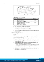
Page 19: ...ncluded in the enclosed pack Dimensions of the centering elements included in the enclosed pack Item Mounting 2 Centering sleeve 4x 14 x 8 6 The screws for mounting the top jaws have to be provided by...

Page 20: ...e unevenness 100 0 02 100 0 05 Mounting The module can be mounted from the front or on the side Assembly options The centering sleeves 4 are included in the enclosed pack Size of centering devices in...

Page 21: ...diameter and max depth of engagement for gripper fastening from the front M8 15 mm 2 Thread diameter and max depth of engagement for gripper fastening from the side M8 14 mm Maximum tightening torques...

Page 22: ...and or damping Observe the diagrams and information in the catalog data sheet NOTE Observe the requirements for the compressed air supply Technical Data 18 In case of compressed air loss cutting off t...

Page 23: ...e two O rings from the enclosed pack 4 3 Mounting the sensor NOTE Observe the assembly and operating manual of the sensor for mounting and connecting The product is equipped for the use of sensors For...

Page 24: ...d radius of the cable catalog Avoid contact of the proximity switches with hard objects and with chemicals in particular nitric acid chromic acid and sulphuric acid The inductive proximity switches ar...

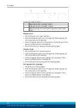
Page 25: ...e front of the gripper until the proximity switch actuates By tightening the screw 101 fix the proximity switch in this position Test the function by closing and opening the gripper Gripper closed Put...

Page 26: ...By tightening the screw 101 fix the proximity switch in this position Test the function by opening and closing the gripper Part gripped I D gripping Clamp the part to be gripped Install the switch cam...

Page 27: ...f 30 Ncm for the set screws NOTE Ferromagnetic material changes the switching positions of the sensor For example Adapter plate made of ordinary steel At ferromagnetic adapter plates First mount the p...

Page 28: ...threaded pin Test the function by closing and opening the gripper Gripper closed Put the Gripper into closed position Push the Magnetic switch 2 2 through the milled opening 3 into the groove until it...

Page 29: ...gripping Clamp the part to be gripped Push the Magnetic switch 1 1 through the milled opening 3 into the groove until it switches Fix the magnetic switch 1 in this position by clamping it in the groo...

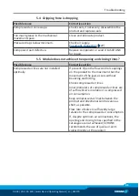
Page 30: ...Possible cause Corrective action Dirt deposits between cover and piston Remove the cover clean the product and regrease it Maintenance 32 Dirt deposits between basic jaws and guidance Disassemble and...

Page 31: ...ssible cause Corrective action Compressed air lines are not installed optimally If present Open the flow control couplings on the product to the maximum that the movement of the jaws occurs without bo...

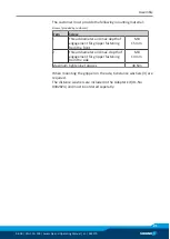
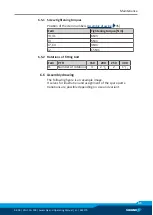
Page 32: ...rden more quickly at temperatures above 60 C leading to possible product damage Reduce the lubricant intervals accordingly Size 150 300 Interval Mio cycles 1 5 6 3 Lubricants Lubrication points basic...

Page 33: ...crews 64 Remove the final cover 71 Remove the reaming bolts 31 Remove the rotary covers 20 Remove the screws 62 Remove the housing covers 6 NOTE The base jaws 3 and the gibs 4 and 14 are individually...

Page 34: ...arts Assembly drawing 35 Seal kit Seal kit 7 Assembly Assembly takes place in the opposite order to disassembly Observe the following Position of the item numbers Assembly drawing 35 Notice the instal...

Page 35: ...wing 35 Item Tightening torque Nm 29 31 6 Nm 33 5 Nm 37 64 3 Nm 62 15 Nm 6 5 2 Rotations of fitting bolt Item PFH 150 200 250 300 31 Number of rotations 3 2 1 2 2 1 1 2 6 6 Assembly drawing The follow...

Page 36: ...8 00 PFH 150 300 Assembly and Operating Manual en 389270 Assembly drawing PFH Wearing part replace during maintenance Included in the seal kit Seal kit can only be ordered completely only PFH 150 PFH...

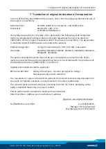
Page 37: ...FH 150 300 pneumatic ID number 0302000 0302020 0302005 0302010 39302000 39302020 39302005 39302010 The partly completed machine may not be put into operation until conformity of the machine into which...

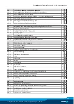
Page 38: ...ssential Requirements 1 1 1 Definitions X 1 1 2 Principles of safety integration X 1 1 3 Materials and products X 1 1 4 Lighting X 1 1 5 Design of machinery to facilitate its handling X 1 1 6 Ergonomi...

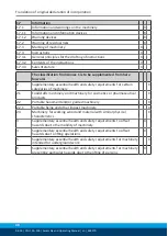
Page 39: ...cking movable guards X 1 4 2 3 Adjustable guards restricting access X 1 4 3 Special requirements for protective devices X 1 5 Risks due to other hazards 1 5 1 Electricity supply X 1 5 2 Static electri...

Page 40: ...safety requirements for certain categories of machinery X 2 1 Foodstuffs machinery and machinery for cosmetics or pharmaceutical products X 2 2 Portable hand held and or guided machinery X 2 2 1 Porta...

Reviews: