Assembly
4.2.10 Mounting programmable magnetic switch MMS-IOL
CAUTION
Risk of damage to the sensor during assembly!
•
Observe the maximal tightening torque.
NOTE
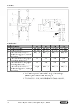
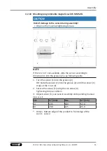
If there is no T-nut available, slide the sensor according to
dimension I1 into the groove (2), see following table.
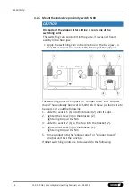
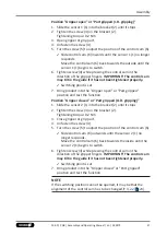
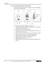
1. Turn the sensor (1) into the groove (2).
OR: Slide the sensor (1) into the groove (2) until the sensor (1)
stops at the T-nut (3).
2. Secure the sensor (1) using the set-screw (4).
Tightening torque: 10 Ncm
3. Adjust sensor (1), see sensor assembly and operating manual.
Dimensions I1
Size
l1* [mm]
Size
l1* [mm]
64
19.5
100
32.0
80
29.0
125
35.0
* Dimen
sion l1
Bottom edge of the product to front edge of the
sensor
33
13.00 | PGB | Assembly and Operating Manual | en | 389275


