background image

28

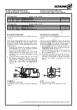
Montage- und Betriebsanleitung für
2-Finger-Parallelgreifer  Type PGN-plus

Assembly and Operating Manual for
2-Finger Parallel Gripper  Type PGN-plus

* Einzelteile sind aufeinander abgestimmt und können nicht vom Kunden

ausgetauscht werden.

GKS:

Greifkraftsicherung

AS:

Außensichern

IS:

Innensichern

SD:

Staubabdeckung

KVZ:

Kraftverstärkungszylinder

HUE:

Schutzhülle

* Individual components are matched to one another so that the customer

should not replace them with different parts.

GKS:

Gripping force safety device

AS:

Safety device O.D. gripping

IS:

Safety device I.D. gripping

SD:

Dust Cover

KVZ:

Power booster cylinder

HUE:

Protective cover

Verschleißteile, empfohlen bei Wartung auszutauschen

Wear parts; replacement during maintenance recommended

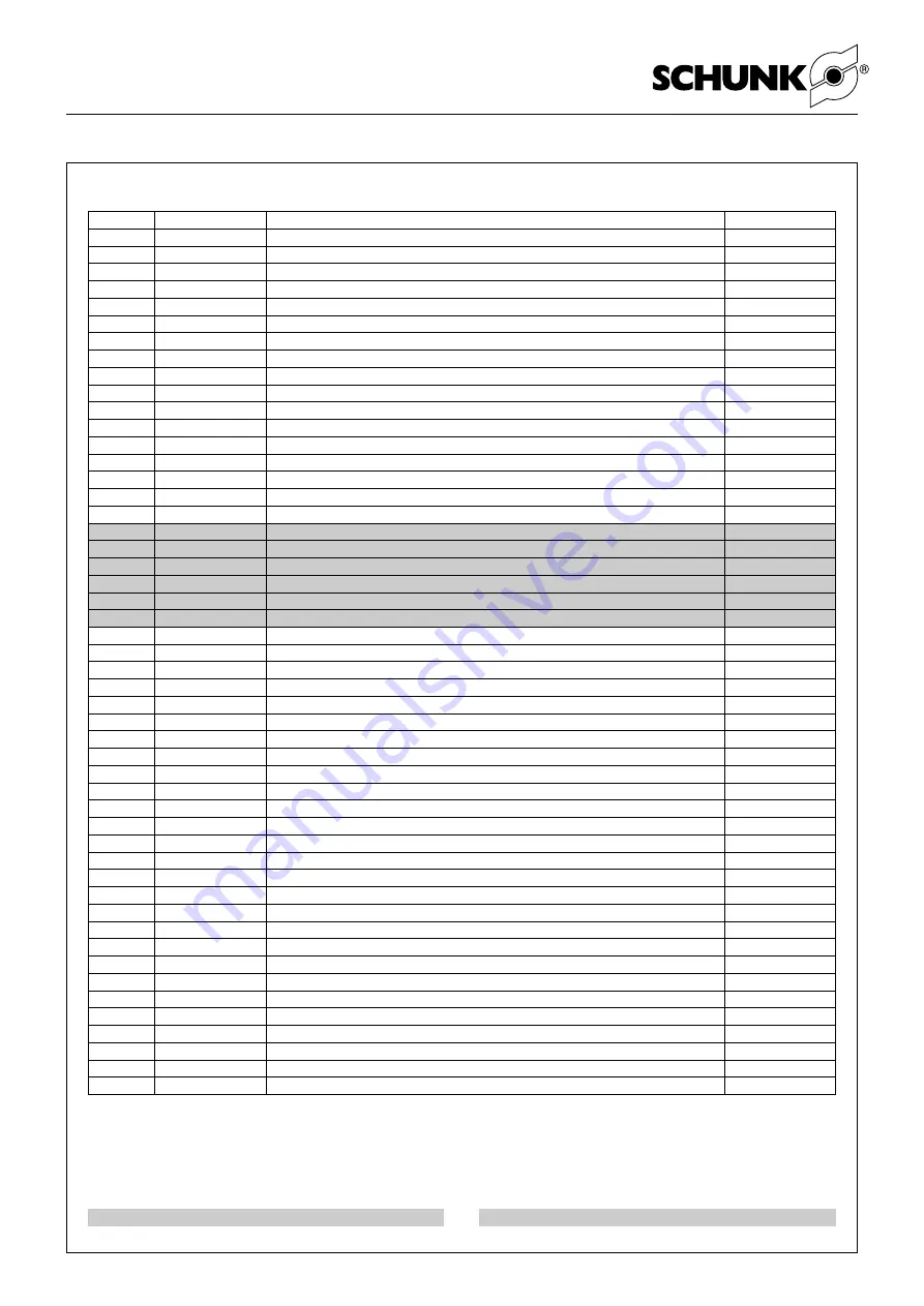
Pos./item

Ident-Nr. / Id.-No.

Bezeichnung / Description

Menge / Quantity

1*

5511 511

Gehäuse / Housing

1

2*

5511 512

Grundbacke - Hub 1 / Base jaw - Stroke 1

2

3

5511 513

Kolben - Hub 1 / Piston - Stroke 1

1

4

5511 514

Deckel ohne GKS / Cover without GKS

1

5

5511 327

Abdeckblech / Cover plate

1

6

5511 515

Zylinderkolben ohne GKS - GKS IS / Cylinder piston without GKS - GKS IS

1

7*

5511 516

Grundbacke - Hub 2 / Base jaw - Stroke 2

2

8

5511 517

Kolben - Hub 2 / Piston - Stroke 2

1

9

5511 518

Deckel GKS / Cover GKS

1

10

5511 519

Zylinderkolben GKS AS / Cylinder piston GKS AS

1

11

5511 488

Distanzbolzen GKS AS / Distance bolt GKS AS

1

15

9937 475

Schaltnocke / Operating cam

2

16

9936 956

Halter für Schaltnocke / Bracket for operating cam

2

17

5503 506

Halter für Näherungsschalter / Bracket for proximity switch

2

19

5509 647

Zentrierhülse Ø 22 - GKS / Centering sleeve Ø 22 - GKS

2

25

9980 808

Druckfeder GKS AS / Pressure spring GKS AS

1

25

9980 805

Druckfeder GKS IS / Pressure spring GKS IS

1

30

9941 907

O-Ring / O-ring    120.25 x 3.53

1

31

9938 273

Quad-Ring / Square ring    29.74 x 3.53

1

32

9937 935

O-Ring / O-ring    140.00 x 2.00

1

33

9611 115

O-Ring / O-ring    18.00 x 1.00    ohne/without GKS - GKS IS

1

33

9611 115

O-Ring / O-ring    18.00 x 1.00    GKS AS

2

34

9611 227

O-Ring / O-ring    5.00 x 1.00

4

40 

9682 123

Senkschraube / Countersunk screw    M16 x 40 - ohne/without GKS - GKS IS

1

41

9907 607

Schraube / Screw    M5 x 16 - ohne/without GKS

8

42

9938 231

Schraube / Screw    M4 x 40    Hub 1 / Stroke 1

2

42

9936 687

Schraube / Screw    M4 x 30    Hub 2 / Stroke 2

2

43

9936 059

Schraube / Screw    M4 x 35    Hub 1 / Stroke 1

2

43

9660 219

Schraube / Screw    M4 x 25    Hub 2 / Stroke 2

2

44

9660 413

Schraube / Screw    M3 x 14

4

45

9981 476

Schraube / Screw    M16 x 80 / GKS AS

1

46

9660 422

Schraube / Screw    M8 x 50 / GKS

4

47

9664 501

Senkschraube / Countersunk screw     M3 x 8

4

48

9936 175

Gewindestift / Set-screw    M5 x 4

6

49

9936 175

Gewindestift / Set-screw    M5 x 4

4

50

5511 496

Gehäuse mit Grundbacken - Hub 1 / Housing with base jaws - Stroke 1

1

50

5511 504

Gehäuse mit Grundbacken - Hub 2 / Housing with base jaws - Stroke 2

1

60

9938 063

Rundmagnet / Round magnet

2

81

5512 998

Abdeckung / Cover   SD

2

82

5513 006

Abdeckblech / Cover plate   SD

1

83

5513 014

Zwischendeckel / Intermediate cover   SD

2

84

5513 022

Zwischenbacke / Intermediate jaw   SD

2

85

5513 024

Dichtbolzen / Sealing bolt   SD

2

86

9939 383

Hülse / Sleeve   Ø 22   SD

4

87

9935 670

O-Ring / O-ring   62.00 x 1.50   SD

2

89

9664 501

Senkschraube / Countersunk screw     M3.0 x 8   SD

8

90

9936 447

Schraube / Screw    M5.0 x 8   SD

4

91

9660 054

Schraube / Screw    M16.0 x 35.00   SD

4

98

5512 050

Beipack ohne GKS / Accessories supplied without GKS

1

99

5512 058

Beipack mit GKS / Accessories supplied with GKS

1

Ersatzteilstückliste   PGN-plus 300

Spare part list   PGN-plus 300

Air-Oil Systems, Inc.  www.airoil.com

Summary of Contents for PGN-plus 100

Page 1: ... be schunk com CANADA SCHUNK Intec Corp Tel 1 905 712 2200 Fax 1 905 712 2210 info ca schunk com www ca schunk com CHINA SCHUNK Precision Machinery Tel 86 571 8672 1000 Fax 86 571 8673 8800 info cn schunk com www cn schunk com CZECH REPUBLIC SCHUNK Intec s r o Tel 420 545229095 Fax 420 545220508 info cz schunk com www cz schunk com DENMARK SCHUNK Intec A S Tel 45 43601339 Fax 45 43601492 info dk s...

Page 2: ...nsichern Version with gripping force safety device for I D gripping 10 8 2 5 Version KVZ Kraftverstärkungszylinder Version KVZ Power booster cylinder 10 8 2 6 Option HUE Schutzhülle Option HUE Protective cover 11 8 3 Schraubenanzugsmomente Screw tightening torques 11 9 Zusammenbauzeichnungen Assembly drawings 12 9 1 Version ohne Staubabdeckung Version without dust cover 12 9 2 Zusammenbau der Stau...

Page 3: ...es protective covers must be used according to EC Machine Directive Point 1 4 1 Sicherheit 1 1 Symbolerklärung Dieses Symbol ist überall dort zu finden wo besondere Gefahren für Personen oder Beschädigungen des Greifers möglich sind 1 2 Bestimmungsgemäßer Gebrauch Der Greifer darf ausschließlich im Rahmen seiner technischen Daten verwendet werden Zur bestimmungsgemäßen Verwendung gehört auch die E...

Page 4: ...ter Seal sets and spare parts lists 11 Es bestehen Gefahren durch herabfallende und herausgeschleuderte Gegenstände Es müssen Vorkehrungen getroffen werden um das Herabfallen oder das Herausschleudern von eventuell gefährlichen Gegenständen bearbeitete Werkstücke Werkzeuge Späne Bruchstücke Abfälle usw zu vermeiden 12 Zusätzliche Bohrungen Gewinde oder Anbauten die nicht als Zubehör von SCHUNK ang...

Page 5: ...mbly CAUTION Before starting assembly of the gripper the power supply must be switched off Please also consider the safety hints on pages 3 and 4 The guide sleeves required for fastening the gripper from the front and for fixing the finger and gripper are contained in the relevant enclosed pack The contents of the enclosed pack are listed in Chapter 10 2 Greiferbefestigung von hinten Gripper faste...

Page 6: ...omplete the stroke Dirt between the cover plate and the chuck piston Dirt between the base jaw and the guide Pressure has dropped below minimum level Cylinder piston magnet has come loose 7 Problemanalyse Der Greifer bewegt sich nicht Luftversorgung überprüfen Mindestdruck unterschritten Luftleitungen vertauscht Näherungsschalter defekt oder falsch eingestellt Nicht benötigte Luftanschlüsse nicht ...

Page 7: ...stelle des Sperrluftanschlusses eingesetzt werden Entfernen Sie hierzu die beiden Gewindestifte für den Sperrluftanschluss Pos 48 und ersetzen Sie diese durch 2 Schmiernippel mit Anschlussgewinde M5 M3 M6 Reduced gripping force Check seals Clean and re lubricate gripper Check the air supply Gripper opens or closes erratically Clean and re lubricate gripper 8 Maintenance and care for item numbers s...

Page 8: ...ifkraftsicherung Außen sichern Bei der Größe PGN plus 380 mit Greifkraftsicherung empfehlen wir dringend die Wartung und den Dichtungswechsel bei SCHUNK durchführen zu lassen Es bestehen Gefahren durch sehr hohe Federkräfte 8 2 Disassembling the gripper For item numbers see chapter 9 Assembly drawings CAUTION It is essential to read and observe the safety instructions on pages 3 and 4 8 2 1 Versio...

Page 9: ...Reihenfolge wie beim Zerlegen Beachten Sie dabei Kapitel 8 1 und die Schraubenanzugs momente Kapitel 8 3 1 Remove the compressed air lines 2 Undo the screws item 47 and then remove the cover plate item 5 3 Mark the position of the piston item 3 8 and the base jaws item 2 7 in the housing CAUTION In the event of a defect the cover item 9 may be spring loaded 4 Clamp the gripper into the vice betwee...

Page 10: ...ung Kapitel 8 2 2 von Punkt 6 bis 9 Der Zusammenbau erfolgt in umgekehrter Reihenfolge Beachten Sie dabei Kapitel 8 1 und die Schraubenanzugsmomente Kapitel 8 3 8 2 4 Version with gripping force safety device for I D gripping With regard to size PGN plus 380 with gripping force maintenance we urgently recommend that you get maintenance and seal replacement done by SCHUNK Danger due to very high sp...

Page 11: ...hülle Pos 74 über das Gehäuse Pos 1 3 Fügen Sie anschließend die Zwischenbacken Pos 72 in die Schutzhülle Pos 74 4 Fixieren Sie die Schutzhülle Pos 74 mit den Schraub schellen Pos 77 an den Zwischenbacken Pos 72 und der Schraubschelle Pos 78 an den Füllstücken Pos 73 und um das Gehäuse Pos 1 5 Die Fixierung der Aufsatzbacken erfolgt über Zentrierhülsen Pos 75 an den Zwischenbacken Pos 72 8 3 Schra...

Page 12: ...s 40 100 nicht bei not for PGN plus 40 125 Pos 12 bei for PGN plus 40 80 1 6 11 60 17 34 25 16 31 44 42 15 19 50 48 43 48 33 8 3 5 47 7 2 12 25 40 30 49 9 46 49 45 30 10 60 33 4 41 46 Version Außensichern Version with safety device O D gripping Version Innensichern Version with safety device I D gripping Version ohne Greifkraftsicherung Version without gripping force safety device 60 Diese Teile s...

Page 13: ...ger Parallelgreifer Type PGN plus Assembly and Operating Manual for 2 Finger Parallel Gripper Type PGN plus 9 2 Zusammenbau der Staubabdeckung 9 2 Assembly of the dust cover 82 85 90 49 81 91 92 86 84 87 83 89 Air Oil Systems Inc www airoil com ...

Page 14: ...pe PGN plus 9 3 Zusammenbau des Kraftverstärkungs zylinders 9 3 Assembling the power booster cylinder 33 nicht bei not for PGN plus 50 80 nicht bei not for PGN plus 50 80 nicht bei not for PGN plus 50 125 nicht bei not for PGN plus 50 125 41 51 34 6 33 65 48 19 12 32 30 4 49 12 32 30 54 46 48 66 31 6 34 Air Oil Systems Inc www airoil com ...

Page 15: ...elgreifer Type PGN plus Assembly and Operating Manual for 2 Finger Parallel Gripper Type PGN plus 9 4 Zusammenbau der Schutzhülle 9 4 Assembling of the protective cover 77 Fingerfixierung Finger fixing 78 76 73 74 72 75 Air Oil Systems Inc www airoil com ...

Page 16: ... 227 O Ring O ring 5 00 x 1 00 4 Pos item Ident Nr Id No Bezeichnung Description Menge Quantity 30 9610 028 Quad Ring Square ring 39 34 x 2 62 1 31 9610 008 Quad Ring Square ring 14 00 x 1 78 1 32 9936 628 O Ring O ring 49 x 1 1 34 9611 163 O Ring O ring 4 00 x 1 00 4 Pos item Ident Nr Id No Bezeichnung Description Menge Quantity 12 9937 444 Flachdichtung Flat seal PGN plus 80 1 30 9910 063 Quad R...

Page 17: ...e ring 34 29 x 5 33 1 32 SNT 006 174 O Ring O ring 185 00 x 2 00 1 33 9611 115 O Ring O ring 18 00 x 1 50 2 34 9611 081 O Ring O ring 6 00 x 1 50 4 Pos item Ident Nr Id No Bezeichnung Description Menge Quantity 30 9610 073 Quad Ring Square ring 120 25 x 3 53 1 31 9938 273 Quad Ring Square ring 29 74 x 3 53 1 32 9937 935 O Ring O ring 140 00 x 2 00 1 33 9611 115 O Ring O ring 18 00 x 1 00 1 34 9611...

Page 18: ... 227 Quad Ring Square ring 5 x 1 1 40 9682 132 Schraube Screw M3 x 6 1 41 9935 985 Schraube Screw M2 5 x 5 4 45 9682 132 Schraube Screw M3 x 6 GKS AS 1 46 9660 408 Schraube Screw M2 5 x 8 4 47 9942 034 Senkschraube Countersunk screw M2 x 5 4 48 9670 505 Gewindestift Set screw M3 x 3 3 49 9670 057 Gewindestift Set screw M2 x 2 5 50 5516 120 Gehäuse mit Grundbacken Housing with base jaws 1 60 9938 1...

Page 19: ... x 6 ohne without GKS AS 4 45 9660 119 Schraube Screw M3 x 12 GKS AS 1 46 9940 607 Schraube Screw M3 x 16 GKS 4 47 9664 032 Senkschraube Countersunk screw M2 5 x 4 4 48 9936 175 Gewindestift Set screw M5 x 4 4 49 9670 505 Gewindestift Set screw M3 x 3 5 50 5512 634 Gehäuse mit Grundbacken Hub 1 Housing with base jaws Stroke 1 1 50 5512 635 Gehäuse mit Grundbacken Hub 2 Housing with base jaws Strok...

Page 20: ...05 Schraube Screw DIN 7984 A2 M3 x 30 4 60 9936 070 Rundmagnet Round magnet ohne without GKS GKS IS 2 60 9937 759 Rundmagnet Round magnet GKS AS 1 65 5513 804 Zwischengehäuse Intermediate housing KVZ 1 66 5513 814 Distanzkolben Distance piston KVZ 1 72 5512757 Zwischenbacke Intermediate jaw PGN 64 PVC HUE 2 73 5512765 Füllstück Filler piece PGN 64 PVC HUE 2 74 9941393 Schutzabdeckung Protective co...

Page 21: ...2 Druckfeder GKS Pressure spring GKS 1 30 9610 063 Quad Ring Square ring 29 82 x 2 62 1 31 9610 007 Quad Ring Square ring 12 42 x 1 78 1 40 9664 003 Senkschraube Countersunk screw M6 x 16 ohne without GKS GKS IS 1 41 9661 505 Schraube Screw M4 x 10 ohne without GKS 4 42 9937 113 Schraube Screw M2 x 14 Hub Stroke 1 2 42 9682 135 Schraube Screw M2 x 10 Hub Stroke 2 2 43 9682 135 Schraube Screw M2 x ...

Page 22: ... Hub 2 Base jaw Stroke 2 2 8 5511 291 Kolben Hub 2 Piston Stroke 2 1 9 5511 299 Deckel GKS Cover GKS 1 10 5511 307 Zylinderkolben GKS AS Cylinder piston GKS AS 1 15 9937 474 Schaltnocke Operating cam 2 16 9936 955 Halter für Schaltnocke Bracket for operating cam 2 17 5503 506 Halter für Näherungsschalter Bracket for proximity switch 2 19 5509 643 Zentrierhülse Ø 10 GKS Centering sleeve Ø 10 GKS 2 ...

Page 23: ...crew M3 x 16 Hub Stroke 2 2 43 9660 003 Schraube Screw M3 x 16 Hub Stroke 1 2 43 9660 119 Schraube Screw M3 x 12 Hub Stroke 2 2 44 9660 413 Schraube Screw M3 x 14 4 45 9660 030 Schraube Screw M8 x 45 GKS AS 1 Ersatzteilstückliste PGN plus 125 Spare part list PGN plus 125 Pos item Ident Nr Id No Bezeichnung Description Menge Quantity 75 9939379 Zentrierhülse Guide sleeve Ø 10 x 6 65 HUE 4 76 966042...

Page 24: ...screw DIN 7991 10 9 M8 x 55 1 60 9937 758 Rundmagnet Round magnet 1 65 5513 807 Zwischengehäuse Intermediate housing KVZ 1 66 5513 817 Distanzkolben Distance piston KVZ 1 72 5512760 Zwischenbacke Intermediate jaw PGN 125 PVC HUE 2 73 5512768 Füllstück Filler piece PGN 125 PVC HUE 2 74 9941396 Schutzabdeckung Protective cover PGN 125 HUE 1 75 9939379 Zentrierhülse Guide sleeve Ø 10 x 6 65 HUE 4 76 ...

Page 25: ... x 4 6 49 9936 175 Gewindestift Set screw M5 x 4 4 50 5511 494 Gehäuse mit Grundbacken Hub 1 Housing with base jaws Stroke 1 1 50 5511 502 Gehäuse mit Grundbacken Hub 2 Housing with base jaws Stroke 2 1 51 9939 222 Senkschraube Countersunk screw DIN 7991 10 9 M10 x 65 1 60 9938 063 Rundmagnet Round magnet 1 65 5513 808 Zwischengehäuse Intermediate housing KVZ 1 66 5513 818 Distanzkolben Distance p...

Page 26: ... ring 85 32 x 3 53 1 31 9610 036 Quad Ring Square ring 25 00 x 3 53 1 32 9936 043 O Ring O ring 106 00 x 2 00 1 33 9935 303 O Ring O ring 14 00 x 1 00 ohne without GKS GKS IS 1 33 9935 303 O Ring O ring 14 00 x 1 00 GKS AS 2 34 9611 227 O Ring O ring 5 00 x 1 00 4 40 9664 033 Senkschraube Countersunk screw M12 x 30 ohne without GKS GKS IS 1 41 9907 607 Schraube Screw M5 x 16 ohne without GKS 8 42 ...

Page 27: ...43 9938 231 Schraube Screw M4 x 30 2 44 9660 413 Schraube Screw M3 x 14 4 45 9980 008 Schraube Screw M16 x 65 1 46 9660 038 Schraube Screw M10 x 50 4 47 9664 501 Senkschraube Countersunk screw M3 x 8 4 48 9936 175 Gewindestift Set screw M5 x 4 6 49 9936 175 Gewindestift Set screw M5 x 4 4 50 5513 856 Gehäuse mit Grundbacken Hub 1 Housing with base jaws Stroke 1 1 50 5513 857 Gehäuse mit Grundbacke...

Page 28: ... GKS AS 1 25 9980 805 Druckfeder GKS IS Pressure spring GKS IS 1 30 9941 907 O Ring O ring 120 25 x 3 53 1 31 9938 273 Quad Ring Square ring 29 74 x 3 53 1 32 9937 935 O Ring O ring 140 00 x 2 00 1 33 9611 115 O Ring O ring 18 00 x 1 00 ohne without GKS GKS IS 1 33 9611 115 O Ring O ring 18 00 x 1 00 GKS AS 2 34 9611 227 O Ring O ring 5 00 x 1 00 4 40 9682 123 Senkschraube Countersunk screw M16 x ...

Page 29: ... 2 43 9660 517 Schraube Screw M4 x 65 2 44 9660 413 Schraube Screw M3 x 14 4 45 9980 008 Schraube Screw M16 x 90 1 46 9941 459 Schraube Screw M10 x 70 4 47 9638 693 Senkschraube Countersunk screw M5 x 12 4 48 9670 520 Gewindestift Set screw M6 x 6 6 49 9936 175 Gewindestift Set screw M5 x 4 4 50 5515 127 Gehäuse mit Grundbacken Hub 1 Housing with base jaws Stroke 1 1 50 5515 128 Gehäuse mit Grundb...

Page 30: ...x 25 PGN plus 64 52 36 27 31 24 42 27 8 5 5 10 23 2 5 7 M5 x 30 PGN plus 80 63 42 32 42 30 52 32 8 5 5 10 25 2 5 6 M5 x 35 PGN plus 100 81 50 38 54 36 66 38 10 6 6 11 30 3 5 7 M6 x 40 l3 A B C l 4 D D d9 l 5 Schnitt Cross section D D d8 l 7 l 8 d7 d6 d5 l 6 l2 d2 C C l 1 Schnitt Cross section C C d2 d3 d4 42 50 11 2 Montagevorrichtung Greifkraftsicherung 11 2 Mounting device for gripping force saf...

Page 31: ...zart nach DIN 40050 IP 67 für die Rundsteckverbindung nur im verschraubten Zustand 12 Accessories on separate order 12 1 Proximity switches NOTE Proximity and magnetic switches are accessories and have to be ordered separately The SCHUNK grippers are designed for the use of magnetic switches type MMS 22 RMS and proximity swit ches type INW 80 S NOTE Make sure that the proximity switches will be pr...

Page 32: ...Gehen Sie weiter vor wie unter Greifer geöffnet von Punkt 2 5 beschrieben CAUTION If grippers are fastened on adapter plates made of ferro magnetic material i e standard constructional steel the gripper has to be mounted on the adapter plate b e f o re the positions of the magnetic switch are adjusted This is absolutely necessary if magnetic materials are used since they are changing the switching...

Page 33: ...er Schraube Pos 17a 2 Stellen Sie den Greifer in Stellung Auf und testen Sie die Funktion Greifer geschlossen 1 Schieben Sie den Näherungsschalter 2 in den Klemmhalter Pos 17 auf Anschlag und befestigen Sie ihn durch Anziehen der Schraube Pos 17a 2 Stellen Sie den Greifer in Stellung Zu und testen Sie die Funktion Teil gegriffen Außengreifen 1 Schieben Sie den Näherungsschalter 2 auf Anschlag in d...

Page 34: ...he screw item 42 again 5 Perform a function test by opening and closing the gripper 6 In case of version with dust cover please close the thread at the lateral cover with the supplied set screws Workpiece gripped I D gripping 1 Move proximity switch 1 to the stop in the bracket item 17 and fasten it by tightening the screw item 17a 2 Clamp the workpiece to be gripped 3 Undo the screw item 42 Untig...

Page 35: ...Distanzscheibe Spacer 1 38 9937 005 Schraube M3 x 30 Screw M3 x 30 1 AS PGN plus 125 2 Ident Nr Id No 301 637 Pos Item Ident Nr Id No Bezeichnung Description Menge Quantity 23 5512 284 Schaltnocke Control Cam 1 26 5512 312 Distanzscheibe Spacer 1 38 9960 424 Schraube M3 x 25 Screw M3 x 25 1 AS PGN plus 160 1 Ident Nr Id No 301 638 Pos Item Ident Nr Id No Bezeichnung Description Menge Quantity 21 5...

Page 36: ...t be removed before the operating cam can be replaced 1 Remove the operating cam for monitoring along with the inductive proximity switch item 15 and the two screws item 42 and 43 from the base jaw item 2 7 2 With the chamfered side to the front insert the operating cam item 21 23 into the base jaw item 2 7 and screw it with the screw provided item 38 3 First insert the spacer item 26 and then fle...

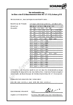
Page 37: ...sierte Normen insbesondere Datum Hersteller Unterschrift Angaben zum Unterzeichner Bezeichnung der Produkte Produkt Typ Produkt Nr 2 Finger Parallelgreifer pneumatisch PGN plus 40 bis PGN plus 380 371 080 371 082 371 084 371 099 371 108 371 149 371 158 371 399 371 408 371 449 371 458 371 459 371 468 371 469 371 478 372 100 372 104 372 150 372 154 3737 1080 3737 1082 3737 1084 3737 1099 3737 1108 3...

Page 38: ...nized standards in particular Date Signature of manufacturer Title of the signatory Name of product Product type Product no 2 Finger Parallel Gripper pneumatic PGN plus 50 to PGN plus 380 371 080 371 082 371 084 371 099 371 108 371 149 371 158 371 399 371 408 371 449 371 458 371 459 371 468 371 469 371 478 372 100 372 104 372 150 372 154 3737 1080 3737 1082 3737 1084 3737 1099 3737 1108 3737 1149 ...

Page 39: ... onze Benelux vestiging Attenzione per l installazione e il funzionamento si prega osservare le istruzioni d uso qui allegate Siamo a Vs disposizione per qualsiasi chiarimento o ulteriore spiegazione dovesse necessitarVi SCHUNK Intec Italia Cuando no pueda leer el manual de instrucciones en inglés o alemán por favor diríjase a su distribuidor SCHUNK más cercano o directa mente a SCHUNK en Alemania...

Reviews: