background image

Maintenance

10.00 | PGN-plus-P | Assembly- and Operating Manual | en | 389753

49

7.3 Lubricants/Lubrication points (basic lubrication)

SCHUNK recommends the lubricants listed.
During maintenance, treat all greased areas with lubricant. Thinly
apply lubricant with a lint-free cloth.

Lubricant point

Lubricant

Metallic sliding surfaces

microGLEIT GP 360

All seals

Renolit HLT 2

Cylinder surfaces

Renolit HLT 2

7.4 Lubricate product

 WARNING

Risk of injury due to moving parts!

When moving the gripper fingers, body parts may get squashed/
hit causing severe injuries.

Do not interfere with moving parts during operation.

Observe position and direction of movement of the gripper
fingers.

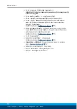
Ø

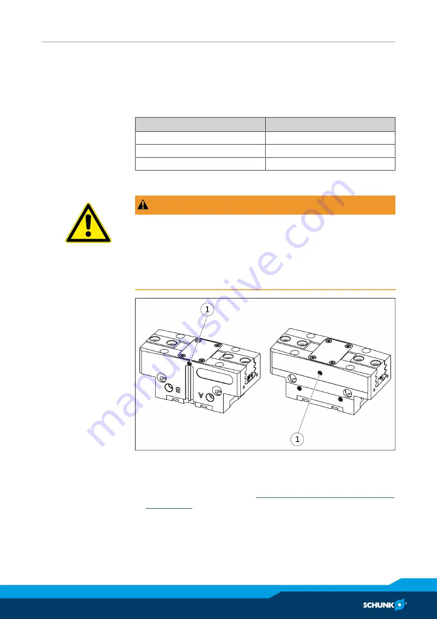
Remove set-screw on an air purge connection (1).

Ø

Screw in lubrication nipple.

Ø

Apply a layer of grease to metallic sliding surfaces of the gripper
using the lubrication nipple, 

Lubricants/Lubrication points (basic

lubrication) 

 [

}

 49].

While lubricating, completely open and close the gripper
alternately.

Ø

Unscrew the lubrication nipple.

Ø

Screw set-screws into both air purge connections (1).

Summary of Contents for PGN-plus-P

Page 1: ...Translation of the original manual Assembly and Operating Manual PGN plus P 2 Finger Parallel Gripper ...

Page 2: ...lterations for the purpose of technical improvement Document number 389753 Version 10 00 30 08 2019 en SCHUNK GmbH Co KG All rights reserved Dear Customer thank you for trusting our products and our family owned company the leading technology supplier of robots and production machines Our team is always available to answer any questions on this product and other solutions Ask us questions and chal...

Page 3: ... 4 Spare parts 10 2 5 Gripper fingers 10 2 6 Environmental and operating conditions 10 2 7 Personnel qualification 10 2 8 Personal protective equipment 11 2 9 Notes on safe operation 12 2 10 Transport 12 2 11 Malfunctions 12 2 12 Disposal 13 2 13 Fundamental dangers 13 2 13 1 Protection during handling and assembly 13 2 13 2 Protection during commissioning and operation 14 2 13 3 Protection agains...

Page 4: ...ing analog MMS 22 A magnetic switch 39 5 4 12 Mounting analog position sensor APS Z80 41 5 4 13 Mount the flexible position sensor FPS 42 5 4 14 Mounting analog position sensor APS M1 45 6 Troubleshooting 46 6 1 Product does not move 46 6 2 Product is not executing the complete stroke 46 6 3 Product opens or closes abruptly 46 6 4 Product does not achieve the opening and closing times 47 6 5 Gripp...

Page 5: ...this manual Illustrations in this manual are provided for basic understanding and may differ from the actual product design In addition to these instructions the documents listed under Applicable documents 6 are applicable 1 1 1 Presentation of Warning Labels To make risks clear the following signal words and symbols are used for safety notes DANGER Danger for persons Non observance will inevitabl...

Page 6: ... applies to the following sizes PGN plus P 40 PGN plus P 50 PGN plus P 64 PGN plus P 80 PGN plus P 100 PGN plus P 125 PGN plus P 160 PGN plus P 200 PGN plus P 240 PGN plus P 300 PGN plus P 380 1 1 4 Variants This operating manual applies to the following variations PGN plus P stroke 1 PGN plus P stroke 2 PGN plus P with gripping force maintenance O D gripping AS PGN plus P with gripping force main...

Page 7: ...g process Open gripper release workpiece and Close gripper grip workpiece 1 3 Scope of delivery The scope of delivery includes 2 Finger Parallel Gripper PGN plus P in the version ordered Accessory pack Content of the accessory pack 2x centering sleeve for gripper fastening 4x centering sleeve for finger fastening 2 x O ring for hose free direct connection ID No of the accessory pack Size ID number...

Page 8: ...of the sealing kit 1x Cylinder piston seal 1x Piston rod seal 1x Cover gasket ID No of the seal kit Size ID number PGN plus P PGN plus P V HT PGN plus P 40 1342290 1342298 PGN plus P 50 1000115 1000116 PGN plus P 64 1000117 1000118 PGN plus P 80 1000119 1000120 PGN plus P 100 1000121 1000122 PGN plus P 125 1000123 1000124 PGN plus P 160 1342256 1342270 PGN plus P 200 1339255 1339273 PGN plus P 240...

Page 9: ...ion in a machine system The applicable guidelines must be observed and complied with The product is intended for industrial and industry oriented use Appropriate use of the product includes compliance with all instructions in this manual 2 2 Not intended use It is not intended use if the product is used for example as a pressing tool stamping tool lifting gear guide for tools cutting tool clamping...

Page 10: ...e that the product and the top jaws are a sufficient size for the application 2 6 Environmental and operating conditions Required ambient conditions and operating conditions Incorrect ambient and operating conditions can make the product unsafe leading to the risk of serious injuries considerable material damage and or a significant reduction to the product s life span See also Technical data 17 2...

Page 11: ...haviour Service personnel of the manufacturer Due to its technical training knowledge and experience service personnel of the manufacturer is able to perform the delegated tasks and to recognize and avoid possible dangers 2 8 Personal protective equipment Use of personal protective equipment Personal protective equipment serves to protect staff against danger which may interfere with their health ...

Page 12: ...prevention and environ mental protection regulations regarding the product s applica tion field 2 10 Transport Handling during transport Incorrect handling during transport may impair the product s safety and cause serious injuries and considerable material damage When handling heavy weights use lifting equipment to lift the product and transport it by appropriate means Secure the product against ...

Page 13: ...n the system If the energy supply is connected do not move any parts by hand Do not reach into the open mechanism or movement area of the product during operation 2 13 1 Protection during handling and assembly Incorrect handling and assembly Incorrect handling and assembly may impair the product s safety and cause serious injuries and considerable material damage Have all work carried out by appro...

Page 14: ...n to avert danger Until the installed monitors become effective it must be assumed that the drive movement is faulty with its action being dependent on the control unit and the current operating condition of the drive Perform maintenance work modifications and attachments outside the danger zone defined by the movement range To avoid accidents and or material damage human access to the movement ra...

Page 15: ... be verified by executing regular safety measurements 2 14 Notes on particular risks DANGER Risk of fatal injury from suspended loads Falling loads can cause serious injuries and even death Stand clear of suspended loads and do not step within their swiveling range Never move loads without supervision Do not leave suspended loads unattended Wear suitable protective equipment WARNING Risk of injury...

Page 16: ...us injury could occur during the base jaw procedure and when breaking or loosening the gripper fingers Wear suitable protective equipment Do not reach into the open mechanism or the movement area of the product WARNING Risk of injury from sharp edges and corners Sharp edges and corners can cause cuts Use suitable protective equipment ...

Page 17: ...e of gripping force with maintenance of gripping force 8 6 5 Pressure range for air purge bar 0 5 1 Ambient conditions and operating conditions Designation PGN plus P Ambient temperature C min max 5 90 V HT 130 Protection class IP 40 SD 64 Noise emission dB A 70 For use in dirty ambient conditions e g sprayed water vapors abrasion or processing dust SCHUNK offers corresponding product options as s...

Page 18: ... and description 4 1 Design 2 Finger Parallel Gripper 1 Air purge connection 2 Base jaw 3 Compressed air main connection 4 Groove for magnetic switch 5 Housing 4 2 Description Universal 2 finger parallel gripper with large gripping force and high maximum moments thanks to multi tooth guidance ...

Page 19: ...ent sufficient reduction and or damping Observe the diagrams and information in the catalog data sheet Ø Check the evenness of the mounting surface Mechanical connection 20 Ø Connect the product via the hose free direct connection Ø OR Connect compressed air lines to the main air connec tions A and B Remove the locking screws Screw in air connections plug connections OR Screw on throttle valve in ...

Page 20: ...data 17 5 2 Connections 5 2 1 Mechanical connection Evenness of the mounting surface The values apply to the whole mounting surface to which the product is mounted Requirements for evenness of the mounting surface Dimensions in mm Edge length Permissible unevenness 100 0 02 100 0 05 Connections at the base jaws Connections at the base jaws Item Mounting PGN plus P 40 50 64 80 100 125 1 Centering s...

Page 21: ...he dust tight version SD the intermediate jaws are screwed onto the base jaws The intermediate jaws can become off while removing the screws Observe during assembly that the intermediate jaws are between the base jaws und the gripper finger Connections at the housing The product can be mounted from three sides Connections at the housing Item Mounting PGN plus P 40 50 64 80 100 125 Side A 1 Mountin...

Page 22: ... strength class 8 8 3 Centering sleeve Ø5 Ø6 Ø8 Ø8 Ø10 Ø12 Item Mounting PGN plus P 160 200 240 300 380 Side A 1 Mounting screw M8 M10 M12 M16 M20 Max depth of engagement from locating surface mm 20 5 20 25 5 31 38 2 Centering sleeve Ø12 Ø14 Ø16 Ø22 Ø28 Side B 4 Bore for mounting screws M6 M8 M10 M12 M16 Mounting screw according to standard DIN EN ISO 4762 2 Centering sleeve Ø12 Ø12 Ø16 Ø22 Ø28 Si...

Page 23: ...8 M10 Max depth of engagement from locating surface mm 13 12 12 12 16 2 Centering sleeve Ø8 Ø10 Ø10 Ø12 Ø14 5 2 2 Pneumatic connection NOTE Observe the requirements for the compressed air supply Technical data 17 In case of compressed air loss cutting off the energy line the components lose their dynamic effects and do not remain in a secure position However the use of a SDV P pressure mainten anc...

Page 24: ... Attachment Open only the air connections that are needed Close unused main air connections using the screw plugs from the enclosed pack For a hose free direction connection use the O rings from the enclosed pack Item Mounting PGN plus P 40 50 64 80 100 125 1 Thread in the main air connections M3 M5 M5 M5 G1 8 G1 8 Max depth of engagement from locating surface mm 4 5 6 6 7 7 2 Thread in the air pu...

Page 25: ... air purge is used in order to make it more difficult for dirt and dust to penetrate into the product and the guiding areas With the dust tight variant SD it is necessary to use the air purge connection in order to achieve the specified protection class 5 3 Attaching additional structure NOTE With the dust tight variant SD no additional structure can be attached Gripper with additional structure 1...

Page 26: ... size of the additional structure may not exceed the recess of the cover Ø Remove the screws 1 from the cover 2 Ø Remove the cover 2 Ø IMPORTANT Ensure that no foreign objects can enter the gripper Attach additional structure within the recess 4 Mechanical connection 20 Use centering sleeves 3 between gripper and additional structure Centering sleeves can be ordered from SCHUNK With sizes 50 100 t...

Page 27: ...ors and are available at schunk com Information on handling sensors is available at schunk com or from SCHUNK contact persons 5 4 1 Overview of sensors Designation PGN plus P 40 50 64 80 100 125 160 200 240 300 380 Inductive proximity switch IN 80 X X X X X X X X X Magnetic switch MMS 22 X X X X X X X X X X X Programmable magnetic switch MMS 22 PI2 X X X X X X X X Programmable magnetic switch MMS ...

Page 28: ...40 AS 11 9 100 AS 27 40 IS 21 9 100 IS 53 50 22 125 30 50 AS 22 125 AS 30 50 IS 38 125 IS 60 64 17 8 160 38 64 AS 17 8 160 AS 33 5 64 IS 35 8 160 IS 78 5 80 25 8 200 40 5 80 AS 25 8 200 AS 34 80 IS 43 8 200 IS 92 2 NOTE The magnetic switch MMS 22 PI1 can be adjusted and taught in two ways Standard mode allows for quick installation on the T nut preset by SCHUNK in the groove or the defined setting...

Page 29: ...ke is defined in the following table The smallest detectable difference in stroke based on the nominal stroke For grippers with X mm nominal stroke per jaw Min query range per jaw min queried stroke difference per jaw X 5 mm 30 of the nominal stroke per jaw X 5 mm to X 10 mm 20 of the nominal stroke per jaw X 10 mm 10 of the nominal stroke per jaw Example Product with 7 mm nominal stroke per jaw 7...

Page 30: ...S M1 APS Z80 Setting dimension l3 of the base jaw 2 up to the front of the switch cam 1 Size Setting dimension l3 mm FPS APS M1 APS Z80 64 1 0 8 0 0 7 64 2 1 1 0 3 8 80 1 2 0 0 80 2 2 6 0 3 3 100 1 2 7 0 1 100 2 3 0 3 8 125 1 3 8 0 1 7 160 1 0 0 0 160 2 4 2 0 7 1 200 1 2 2 0 0 200 2 7 5 0 3 6 240 1 4 0 2 5 240 2 8 2 0 4 6 300 1 0 0 300 2 12 3 0 8 8 380 1 0 0 380 2 18 9 0 16 5 ...

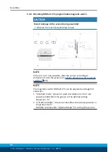
Page 31: ... stops Ø Tighten the screw 3 on the bracket 2 Tightening torque 0 2 Nm Ø Bring product into the open or closed position and test the function Position Part gripped O D gripping or Part gripped I D gripping Ø Variant dust protection SD remove the sealing bolts from the bracket and unscrew the set screw from the side cover Ø Slide the sensor 1 1 through the bracket 2 and into the housing until it st...

Page 32: ...ol cam 6 inwards until the sensor 1 no longer responds Move the control cam 6 back towards the outside until the sensor 1 begins to switch Ø Screw the expander bolt 4 back in to fix the switching point For tightening torque see following table Ø Open the product and close it again in order to test its function Ø Variant dust protection SD Screw in set screw into the side cover Ite m Mounting PGN p...

Page 33: ...Pull the sensor 1 1 back again slowly until it switches Ø Secure the sensor 1 1 using the set screw 4 Tightening torque 10 Ncm Ø Bring product into the Gripper open or Part gripped position and test the function Position Gripper closed or Part gripped O D gripping Ø Bring product in the position in which it is to be set Ø If necessary remove T nut 3 Ø Turn the sensor 2 1 into the groove 2 OR Slide...

Page 34: ...htening torque NOTE If there is no T nut available slide the sensor according to dimension I1 into the groove 2 Setting dimensions for magnetic switches 28 Ø Turn the sensor 1 into the groove 2 OR Slide the sensor 1 into the groove 2 until the sensor 1 stops at the T nut 3 Ø Secure the sensor 1 using the set screw 4 Tightening torque 10 Ncm Ø Adjust sensor 1 see sensor assembly and operating manua...

Page 35: ...ghtening torque NOTE If there is no T nut available slide the sensor according to dimension I1 into the groove 2 Setting dimensions for magnetic switches 28 Ø Turn the sensor 1 into the groove 2 OR Slide the sensor 1 into the groove 2 until the sensor 1 stops at the T nut 3 Ø Secure the sensor 1 using the set screw 4 Tightening torque 10 Ncm Ø Adjust sensor 1 see sensor assembly and operating manu...

Page 36: ...ilable slide the sensor according to dimension I1 into the groove 2 Setting dimensions for magnetic switches 28 NOTE The magnetic switch MMS 22 PI1 can be adjusted and taught in two ways Standard mode allows for quick installation on the T nut preset by SCHUNK in the groove or the defined setting dimension l1 In Optimal Mode the sensor identifies the optimal position in the groove itself SCHUNK re...

Page 37: ...ng tool to the sensor 1 1 to confirm the position The sensor 1 1 has been taught in Ø Repeat steps for sensor 2 Alternatively for size 40 160 except size 50 Setting the sensor in Standard mode Ø Turn the sensor 1 1 into the groove 2 OR Slide the sensor 1 1 into the groove 2 until the sensor 1 1 stops at the T nut 3 Ø Secure the sensor 1 1 using the set screw 4 Tightening torque 10 Ncm Ø Adjust sen...

Page 38: ...ing torque NOTE If there is no T nut available slide the sensor according to dimension I1 into the groove 2 Setting dimensions for magnetic switches 28 Ø Turn the sensor 1 into the groove 2 OR Slide the sensor 1 into the groove 2 until the sensor 1 stops at the T nut 3 Ø Secure the sensor 1 using the set screw 4 Tightening torque 10 Ncm Ø Adjust sensor 1 see sensor assembly and operating manual ...

Page 39: ...rn the sensor 1 into the groove 2 OR Slide the sensor 1 into the groove 2 until the sensor 1 stops at the T nut 3 Ø Secure the sensor 1 using the set screw 4 Tightening torque 10 Ncm Ø Adjust sensor 1 see sensor assembly and operating manual Sizes 50 200 During the monitoring the first and last 15 of the nominal stroke will not produce a change in the analog signal It is therefore not possible to ...

Page 40: ...Ncm NOTE Only valid for size 50 The gripper is too fast without throttling which means that teaching the sensor does not work reliably Fixed throttle valves or other throttle valves with a diameter of 0 8 mm can be used for the teaching process ID number throttle reduction M5 0 8 9953035 Ø Mount a throttle reduction M5 0 8 5 at both main connections A and B Ø Adjust sensor 1 see Translation of Sen...

Page 41: ...signal With O D gripping the Gripper closed position and with I D gripping the Gripper opened position cannot be queried Should you have questions do not hesitate to contact SCHUNK Actual signal Optimum signal Analog signal V Stroke mm Analog signal on O D gripping Analog signal V Stroke mm Actual signal Optimum signal Analog signal on I D gripping Variant Dust tight Before attaching the sensor re...

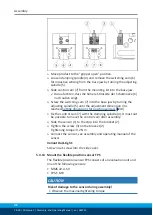
Page 42: ...ment dimension I3 is reached Setting dimensions for position sensors 30 Ø Fix the control cam 7 with the clamping spindle 4 It must not be possible to move the control cam after assembly Ø Slide the sensor 1 to the stop into the bracket 2 Ø Tighten the screw 3 on the bracket 2 Tightening torque 0 2 Nm Ø Connect the sensor see assembly and operating manual of the sensor Variant Dust tight Screw in ...

Page 43: ...unting the MMS 22 A 5V Note In order to mount the sensor MMS 22 A 5V no additional attachment kit is required Ø Assembling the sensor Mounting analog MMS 22 A magnetic switch 39 Ø Connect the control unit output and adjust the sensor see assembly and operating manual of the sensor ...

Page 44: ... sensing from the base jaw by turning the adjusting spindle 5 Ø Slide control cam 7 from the mounting kit into the base jaw Ø Screw the switching cam 7 into the base jaw by turning the adjusting spindle 5 until the adjustment dimension I3 is reached Setting dimensions for position sensors 30 Ø Fix the control cam 7 with the clamping spindle 4 It must not be possible to move the control cam after a...

Page 45: ...ng cam 6 for inductive sensing from the base jaw by turning the adjusting spindle 5 Ø Slide control cam 7 from the mounting kit into the base jaw Darauf achten dass die höhere Stirnseite der Schaltnocke 6 nach außen zeigt Ø Screw the switching cam 7 into the base jaw by turning the adjusting spindle 5 until the adjustment dimension I3 is reached Setting dimensions for position sensors 30 Ø Fix the...

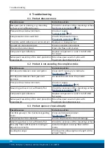
Page 46: ...le cause Corrective action Dirt deposits between cover and piston Clean and if necessary re lubricate Maintenance 48 Dirt deposits between basic jaws and guidance Disassemble and clean the product Pressure drops below minimum Check air supply Pneumatic connection 23 Mounting surface is not sufficiently flat Check the evenness of the mounting surface Mechanical connection 20 Component part defectiv...

Page 47: ... and closing times specified in the catalogue are not achieved SCHUNK recommends the use of quick air vent valves directly at the product Compressed air can escape Check seals if necessary disassemble the product and replace seals Component part defective Replace component or send it to SCHUNK for repair Too much grease in the mechanical movement space Clean and lubricate product Maintenance 48 Lo...

Page 48: ...ts for special ambient conditions are excluded e g higher temperatures dirty environment If products are not used at room temperature or in special ambient conditions the following maintenance intervals apply Interval million cycles Maintenance work 10 Clean the product dry without a degreasing agent check for damage and wear 10 If necessary Replace seals Replace seals 50 10 Treat all grease areas...

Page 49: ...G Risk of injury due to moving parts When moving the gripper fingers body parts may get squashed hit causing severe injuries Do not interfere with moving parts during operation Observe position and direction of movement of the gripper fingers Ø Remove set screw on an air purge connection 1 Ø Screw in lubrication nipple Ø Apply a layer of grease to metallic sliding surfaces of the gripper using the...

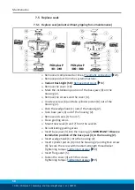
Page 50: ...er piston 8 out of the housing 2 Ø Push the wedge hook 1 out of the housing 2 Ø Take base jaws 3 out of the housing 2 Ø Remove old seals 9 5 and 7 Ø Clean guiding areas Ø Mount new seals 9 and 7 from the seal kit Ø Re lubricating guiding areas Ø Insert base jaws 3 into the housing 2 IMPORTANT Observe installation position of the base jaws 3 in the housing 2 Ø Insert wedge hook 1 into the housing 2...

Page 51: ...Remove all compressed air lines Pneumatic connection 23 Ø Remove product from the system machine Ø Variant Dust tight SD Remove dust cover 54 Ø Remove the cover 12 Ø Mark the installation position of the base jaws 3 on the housing 11 Ø Unscrew the screws and remove the cover 6 Ø IMPORTANT The cylinder piston is under spring tension Remove carefully Unscrew screw 8 carefully and take cylinder pisto...

Page 52: ...8 and secure with medium strength threadlocker Tightening torque Tightening torques 55 Ø Place cylinder pistons 5 on the assembly device 13 slide towards the housing and tighten screw 8 Secure the screw with medium strength threadlocker Tightening torque Tightening torques 55 Ø Insert flat gasket 7 Ø Fasten the cover 6 with the screws Tightening torque Tightening torques 55 Ø Variant Dust tight SD...

Page 53: ... 8 and take cylinder piston 4 out of the housing 10 Ø Push the wedge hook 1 out of the housing 10 Ø Take base jaws 3 out of the housing 10 Ø Remove old seals 2 6 and 9 Ø Clean guiding areas Ø Attach new seals 2 and 9 from the seal kit Ø Re lubricating guiding areas Ø Insert base jaws 3 into the housing 10 IMPORTANT Observe installation position of the base jaws 3 in the housing 10 Ø Insert wedge h...

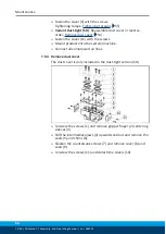
Page 54: ...ver 11 with the screws Ø Mount product onto the system machine Ø Connect all compressed air lines 7 5 4 Remove dust cover The dust cover is only included in the dust tight version SD Ø Unscrew the screws 1 and remove gripper finger 2 centering sleeves 3 Ø Pull the intermediate jaws 4 upwards and out and remove the seals 5 and shims 6 Ø Slacken the countersunk screws 7 and remove cover 8 and seals ...

Page 55: ...2 0 27 PGN plus P 50 1 2 1 2 PGN plus P 64 6 1 1 2 PGN plus P 80 10 3 1 PGN plus P 100 15 3 1 PGN plus P 125 25 3 1 PGN plus P 160 49 2 2 PGN plus P 200 65 5 4 3 PGN plus P 240 85 4 3 PGN plus P 300 380 without GKS Tightening torque for screws details in Nm Size Item 40 Item45 Item 41 Item 46 PGN plus P 300 1 2 120 6 PGN plus P 300 AS 150 25 PGN plus P 300 IS 120 25 PGN plus P 380 1 2 200 10 PGN p...

Page 56: ...Maintenance 56 10 00 PGN plus P Assembly and Operating Manual en 389753 7 7 Assembly drawing PGN plus P 40 240 standard ...

Page 57: ...Maintenance 10 00 PGN plus P Assembly and Operating Manual en 389753 57 PGN plus P 300 380 standard ...

Page 58: ...Maintenance 58 10 00 PGN plus P Assembly and Operating Manual en 389753 PGN plus P 40 240 with maintenance of gripping force O D gripping A and I D gripping B ...

Page 59: ...Maintenance 10 00 PGN plus P Assembly and Operating Manual en 389753 59 PGN plus P 300 380 with maintenance of gripping force O D gripping A and I D gripping B ...

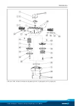
Page 60: ...Maintenance 60 10 00 PGN plus P Assembly and Operating Manual en 389753 Variant dust tight SD ...

Page 61: ... Finger Parallel Gripper PGN plus P pneumatic ID number 0318448 39318573 The partly completed machine may not be put into operation until conformity of the machine into which the partly completed machine is to be installed with the provisions of the Machinery Directive 2006 42 EC is confirmed Applied harmonized standards especially EN ISO 12100 2010 Safety of machinery General principles for desig...

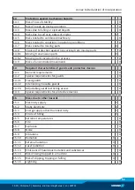
Page 62: ...for the overall machine Fulfilled for the scope of the partly completed machine Not relevant 1 1 Essential Requirements 1 1 1 Definitions X 1 1 2 Principles of safety integration X 1 1 3 Materials and products X 1 1 4 Lighting X 1 1 5 Design of machinery to facilitate its handling X 1 1 6 Ergonomics X 1 1 7 Operating positions X 1 1 8 Seating X 1 2 Control Systems 1 2 1 Safety and reliability of c...

Page 63: ...Risks of uncontrolled movements X 1 4 Required characteristics of guards and protective devices 1 4 1 General requirements X 1 4 2 Special requirements for guards X 1 4 2 1 Fixed guards X 1 4 2 2 Interlocking movable guards X 1 4 2 3 Adjustable guards restricting access X 1 4 3 Special requirements for protective devices X 1 5 Risks due to other hazards 1 5 1 Electricity supply X 1 5 2 Static elec...

Page 64: ...ation from Annex 1 is to be supplemented from here forward 2 Supplementary essential health and safety requirements for certain categories of machinery X 2 1 Foodstuffs machinery and machinery for cosmetics or pharmaceutical products X 2 2 Portable hand held and or guided machinery X 2 2 1 Portable fixing and other impact machinery X 2 3 Machinery for working wood and material with similar physica...

Reviews: