background image

Technical data

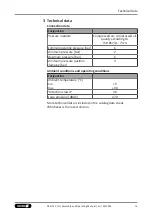
3 Technical data

Connection data

Designation

Pressure medium

Compressed air, compressed air

quality according to 

ISO 8573-1: 7:4:4

Nominal operating pressure [bar]

6

Minimum pressure [bar]

2

Maximum pressure [bar]

6

Minimum pressure position
clamping [bar]

4

Ambient conditions and operating conditions

Designation

Ambient temperature [°C]
min.
max.

+5

+90

Protection class IP

30

Noise emission [dB(A)]

≤70

More technical data is included in the catalog data sheet.
Whichever is the latest version.

15

02.00 | PLG | Assembly and Operating Manual | en | 1517334

Summary of Contents for PLG 120

Page 1: ...Translation of Original Operating Manual Assembly and Operating Manual PLG Configurable Pneumatic 2 Finger Long Stroke Gripper...

Page 2: ...on 02 00 08 11 2022 en Dear Customer Thank you for trusting our products and our family owned company the leading technology supplier of robots and production machines Our team is always available to...

Page 3: ...2 8 Notes on safe operation 10 2 9 Transport 11 2 10 Malfunctions 11 2 11 Disposal 11 2 12 Fundamental dangers 11 2 12 1 Protection during handling and assembly 12 2 12 2 Protection during commission...

Page 4: ...ct does not achieve the opening and closing times 35 7 6 Variant IOL 35 7 6 1 No communication with the product 35 8 Maintenance 36 8 1 Safety 36 8 2 Observation of the maintenance and lubrication int...

Page 5: ...lustrations in this manual are intended to provide a basic understanding and may deviate from the actual version 1 1 1 Presentation of Warning Labels To make risks clear the following signal words and...

Page 6: ...can be downloaded from www mayr com 1 1 4 Sizes and variants This manual applies to the following sizes and variants PLG 30 Size 20 30 50 75 120 Stroke per jaw 100 mm 400 mm freely selectable in incr...

Page 7: ...nger Long Stroke Gripper PLG in the version ordered Assembly and operating manual for the product including declaration of incorporation Accessory pack Content of the accessory pack 8 x centering slee...

Page 8: ...The product can be used within the permissible load limits and technical data for holding workpieces during simple machining operations but is not a clamping device according to EN 1550 1997 A1 2008 A...

Page 9: ...s and significant property damage All work may only be performed by qualified personnel Before working with the product the personnel must have read and understood the complete assembly and operating...

Page 10: ...les when handling hazardous substances Wear close fitting protective clothing and also wear long hair in a hairnet when dealing with moving components 2 8 Notes on safe operation Incorrect handling of...

Page 11: ...ct after a malfunction to establish whether it still functions properly and no increased risks have arisen 2 11 Disposal Handling of disposal The incorrect handling of disposal may impair the product...

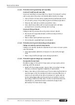
Page 12: ...ed loads unattended 2 12 2 Protection during commissioning and operation Falling or violently ejected components Falling and violently ejected components can cause serious injuries and even death Take...

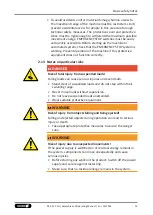
Page 13: ...ended loads Falling loads can cause serious injuries and even death Stand clear of suspended loads and do not step within their swiveling range Never move loads without supervision Do not leave suspen...

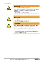
Page 14: ...open mechanism or the movement area of the product WARNING Risk of injury from sharp edges and corners Sharp edges and corners can cause cuts Use suitable protective equipment WARNING Risk of injury f...

Page 15: ...ar 6 Minimum pressure bar 2 Maximum pressure bar 6 Minimum pressure position clamping bar 4 Ambient conditions and operating conditions Designation Ambient temperature C min max 5 90 Protection class...

Page 16: ...oaded from ioddfinder io link com Designation IDWE MxxMP NMS A0 Contrinex material number 330 020 494 Operating voltage VDC min max 10 30 Max ripple Ue 20 Max current on contact mA 200 Voltage drop V...

Page 17: ...achment kit for inductive proximity switch incl guide rail 4 Stop for stroke limitation and cam switch for inductive monitoring 5 Base jaw 6 Main compressed air connection 7 1 Compressed air connectio...

Page 18: ...r fingers By pressure actuation of the opposite piston the base jaws are guided by a carrier on the piston and are set in motion The synchronization of the jaw stroke is done with a rack and pinion pr...

Page 19: ...rt threads Wear appropriate safety equipment Left without adapter plate Right one piece adapter plate 1 Fasten eye bolts to the threads through holes 1 provided for this purpose Note Eyebolts are not...

Page 20: ...ins in the system WARNING Risk of injury from falling of the product During transport and assembly the product may fall down and cause serious injuries Secure unit with adequately sized straps Use tra...

Page 21: ...he gripper fingers to the base jaws 6 2 1 21 3 Connect the sensor if necessary 6 2 3 29 6 2 Connections 6 2 1 Mechanical connection 6 2 1 1 Connections on the housing Mounting the gripper The product...

Page 22: ...75 120 1 Thread M8 M10 M12 M16 Required number of screws piece 8 16 Mounting screws according to standard DIN EN ISO 4762 Mounting screw strength class 12 9 Max tightening torque Nm 43 82 150 230 Max...

Page 23: ...ng screws M8 M10 M12 M16 Required number of screws piece 8 Mounting screws according to standard DIN EN ISO 4762 Mounting screw strength class 12 9 Max tightening torque Nm 43 82 150 230 2 Cylindrical...

Page 24: ...SO 4762 Mounting screw strength class 12 9 Max tightening torque Nm 43 82 150 230 3 Cylindrical pin mm 6 8 10 12 Number of cylindrical pins required piece 2 1 Remove screws 2 and cylindrical pin 3 and...

Page 25: ...25 Complete adapter plate EN ISO 9409 1 125 6 M10 ISO160 M10 Complete adapter plate EN ISO 9409 1 160 6 M10 ISO160 M12 Complete adapter plate EN ISO 9409 1 160 11 M12 ISO200 M12 Complete adapter plate...

Page 26: ...ns at the base jaws Item Mounting 20 30 50 75 120 1 Thread in base jaws M6 M8 M10 M12 Required number of screws per base jaw piece 9 Mounting screw strength class 12 9 Max depth of engagement from loc...

Page 27: ...ke sure that no residual energy remains in the system NOTICE Damage to the gripper is possible If the maximum permissible finger weight or the permissible mass moment of inertia of the fingers is exce...

Page 28: ...connections A open B close 2 Compressed air connection for position clamping quick air relief valve Note In the de energized state the position clamping is activated 3 15 3 Main connections when using...

Page 29: ...Maximum cable length 20 m Make sure that all components are properly grounded Components of the electrical connection Plug connector product Plug connector provided by the customer Connector 4 pin M1...

Page 30: ...d air or energy supply No workpiece is gripped 1 Loosen sleeve 2 SW24 and unscrew 2 Loosen the set screw 3 and pull the sensor 1 out of the sleeve 2 3 Connect IO Link cable to sensor 3 Installing the...

Page 31: ...mbly and operating manual and catalog datasheet are included in the scope of delivery for the sensors and are available at schunk com Information on handling sensors is available at schunk com or from...

Page 32: ...d with sensors steps 1 3 are omitted 1 Loosen the screw 4 on the bracket 2 2 Slide the sensor 1 to the stop in the bracket 2 3 Tighten the screw 4 on the bracket 2 Tightening torque 0 2 Nm 4 Put produ...

Page 33: ...ultaneously on both sides Moving the freely positionable stop 1 Loosen screws 1 and move stop 2 up to 12 5 mm 2 Tighten screws 1 Offsetting the freely positionable stop 1 Remove the screws 1 2 Mount t...

Page 34: ...ed air connections Position clamping not released Check air supply 3 15 Component part defective Replace component or send it to SCHUNK for repair 7 2 Product does not execute a complete stroke Possib...

Page 35: ...cing and hitting Check compressed air lines Inner diameters of compressed air lines are of sufficient size in relation to compressed air consumption Keep compressed air lines between the product and d...

Page 36: ...priate aids to lift and handle the product Take safety measures that prevent the product from falling Wear suitable protective equipment Original spare parts Use only original spare parts of SCHUNK wh...

Page 37: ...ation on the safety data sheet of the lubricant SCHUNK recommends the lubricants listed Provably equivalent lubricants can also be used If different lubricants are used than the recommended ones a com...

Page 38: ...get squashed hit causing severe injuries Do not interfere with moving parts during operation Observe position and direction of movement of the gripper fingers 1 Supply the pinion gear rack and linear...

Page 39: ...any work on the product Switch off the power supply and secure against restarting Make sure that no residual energy remains in the system Disconnect the entire energy supply from the product discharg...

Page 40: ...duct Product designation Configurable Pneumatic 2 Finger Long Stroke Gripper PLG The partly completed machine may not be put into operation until conformity of the machine into which the partly comple...

Page 41: ...the System Integrator for the overall machine Fulfilled for the scope of the partly completed machine Not relevant 1 1 Essential Requirements 1 1 1 Definitions X 1 1 2 Principles of safety integration...

Page 42: ...s of uncontrolled movements X 1 4 Required characteristics of guards and protective devices 1 4 1 General requirements X 1 4 2 Special requirements for guards X 1 4 2 1 Fixed guards X 1 4 2 2 Interloc...

Page 43: ...2 Supplementary essential health and safety requirements for certain categories of machinery X 2 1 Foodstuffs machinery and machinery for cosmetics or pharmaceutical products X 2 2 Portable hand held...

Page 44: ...KG Clamping and gripping technology Bahnhofstr 106 134 D 74348 Lauffen Neckar Tel 49 7133 103 0 Fax 49 7133 103 2399 info de schunk com schunk com Folgen Sie uns I Follow us 11 2022 2022 SCHUNK GmbH C...

Reviews: