Assembly
06.00 | PPU-P | Assembly and Operating Manual | en | 389323
27
Mounting of energy
hose mounting kit
Ø
Remove front cover plate.
Ø
Remove plug (1) from cover.
Ø
Attach mount (3) to cantilever arm using cylindrical screws (4).
Ø
Screw threaded hose couplings (5) with metal lock nuts (6) to
the mount or from inside to the cover.
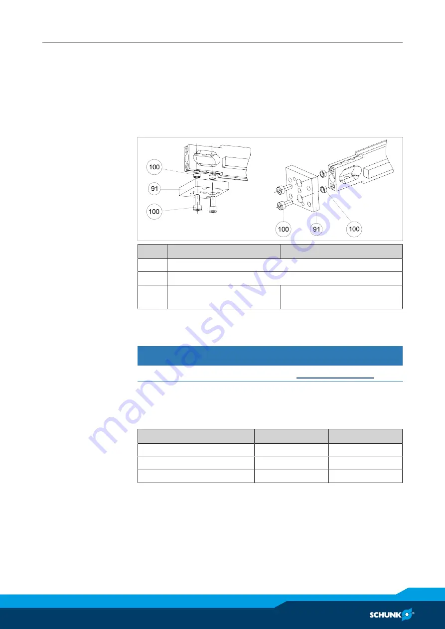
4.4.4 Mounting of adapter plate mounting kit AS-PPU-P...-APL
Item
PPU-P 10
PPU-P 30
91*
Adapter plate
100 **
Centering sleeve
195*
Screw, ISO 4762
M4x10 / 2x
Screw, ISO 4762
M5x12 / 2x
* Optional adapter plate included
** Included
CAUTION
See instructions for attachment of loads,
4.5 Adjusting end positions and shock absorbers
The end positions can be adjusted separately from each other,
both horizontally and vertically.
PPU-P 10
PPU-P 30
Horizontal adjustment range
Each 12 mm
Each 18 mm
Vertical adjustment range
Each 15 mm
Each 20 mm
Maximum vertical difference
8 mm
10 mm


