background image


Technical data / Turning the PEW soft interchangeable inserts 


03.00|Quick-Change Jaw System |en 

13 


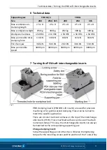
Technical data 


Supporting jaw 

TRP-M / Z 

TRP-G 

Size 

200 

250 / 315 

200 

250 

315 

Max. workpiece un-

clamping length 

2.5 x D 

2.5 x D 

2.5 x D 

2.5 x D 

2.5 x D 

Max. workpiece weight 

250 kg 

300 kg 

250 kg 

300 kg 

300 kg 

Workpiece hardness 

 50 HRC 

≤ 50 HRC


≤ 50 HRC


≤ 50 HRC


≤ 50 HRC


Max. permissible total 

clamping force 

110 kN 

180 kN 

80 kN 

115 kN 

160 kN 

Per chuck jaw 

36.6 kN 

60.0 kN 

26.0 kN 

38.0 kN 

53.0 kN 

Max. permissible 

speed 

3000 rpm 

3000 rpm 

3000 rpm 

3000 rpm 

3000 rpm 


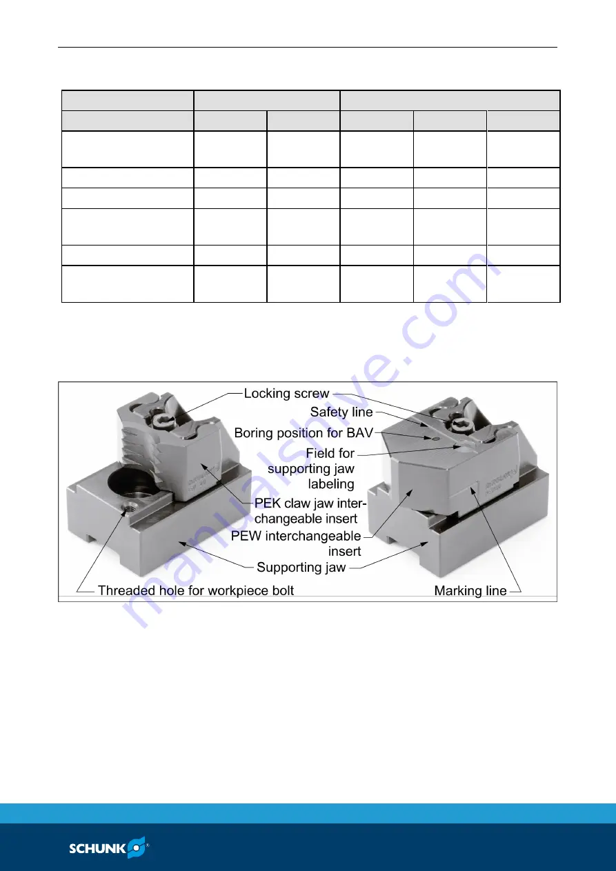
Turning the PEW soft interchangeable inserts 


Fig. 2 

PEW clamping inserts (PRONTO soft inserts) are used for precision 

machining or for gentle second clamping. These can be turned to 

match the specific application. 
There are circular machined surfaces on the top of the interchange-

able inserts (PEW). These machined surfaces can be used to attach 

numerical stamps. This way, the interchangeable inserts can always 

be matched to the corresponding supporting jaw. 

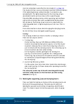
Change clamping insert:


Screw the supporting jaw onto the chuck. Observe the tightening 

torque for the mounting screws and the position of the T-nuts (they 

Summary of Contents for PRONTO

Page 1: ...Original Betriebsanleitung PRONTO Backenschnellwechselsystem Montage und Betriebsanleitung Superior Clamping and Gripping ...

Page 2: ...07 Auflage 03 00 02 06 2017 de SCHUNK GmbH Co KG Alle Rechte vorbehalten Sehr geehrter Kunde wir gratulieren zu Ihrer Entscheidung für SCHUNK Damit haben Sie sich für höchste Präzision hervorragende Qualität und besten Service entschieden Sie erhöhen die Prozesssicherheit in Ihrer Fertigung und erzielen beste Bearbeitungsergebnisse für die Zufriedenheit Ihrer Kunden SCHUNK Produkte werden Sie bege...

Page 3: ...icht bestimmungsgemäße Verwendung 6 2 3 Hinweise auf besondere Gefahren 7 2 4 Umgebungs und Einsatzbedingungen 9 2 4 1 Anforderungen an die Wechseleinsätze 10 2 4 2 Wesentliche Veränderungen 11 2 5 Personalqualifikation 11 2 6 Persönliche Schutzausrüstung 11 3 Gewährleistung 12 4 Schrauben Drehmomente 12 5 Lieferumfang 12 5 1 Zubehör 12 6 Technische Daten 13 7 Ausdrehen der weichen Wechseleinsätze...

Page 4: ...tung Abbildungen in dieser Anleitung dienen dem grundsätzlichen Ver ständnis und können von der tatsächlichen Ausführung abweichen Neben dieser Anleitung gelten die aufgeführten Dokumente unter 1 2 Seite 5 Darstellung der Warnhinweise Zur Verdeutlichung von Gefahren werden in den Warnhinweisen folgende Signalworte und Symbole verwendet GEFAHR Gefahren für Personen Nichtbeachtung führt sicher zu ir...

Page 5: ...en Spitzverzahnt metrisch zoll Trägerbacke TRP M 185 200 1 Trägerbacke TRP Z 200 1 Trägerbacke TRP M 185 200 2 Trägerbacke TRP Z 200 2 Trägerbacke TRP M 185 200 3 Trägerbacke TRP Z 200 3 Trägerbacke TRP M 250 1 Trägerbacke TRP Z 250 315 1 Trägerbacke TRP M 250 2 Trägerbacke TRP Z 250 315 2 Trägerbacke TRP M 250 3 Trägerbacke TRP Z 250 315 3 Trägerbacke TRP M 250 315 1 Trägerbacke TRP M 250 315 2 T...

Page 6: ...Daten verwendet werden 6 Seite 13 Das Produkt ist für industrielle und industrienahe Anwendungen bestimmt Zur bestimmungsgemäßen Verwendung gehört auch das Ein halten aller Angaben in dieser Anleitung Die Höchstdrehzahl des Spannfutters und die notwendige Spannkraft muss vom Betreiber für die jeweilige Spannaufgabe nach den jeweils gültigen Normen bzw technischen Vorgaben des Herstellers ermittelt...

Page 7: ...iner von ihnen durchgeführten und do kumentierten Gefährdungsermittlung und Risikobeurteilung dafür sorgen dass durch geeignete Maßnahmen bis zum Still stand der Maschine und der Sicherung des Werkstückes z B durch einen Kran oder ein geeignetes Hebezeug die Spann kraft des Spannfutters erhalten bleibt Die Maschinen und Einrichtungen müssen den Mindestan forderungen der EG Maschinenrichtlinie ents...

Page 8: ...ungspersonal bei über schreiten der Höchstdrehzahl des Spannfutters durch Werk stückverlust und wegfliegende Teile Kann die Werkzeugmaschine oder die technische Einrichtung eine höhere Drehzahl als die Höchstdrehzahl des Spannfutters erreichen muss eine sichere Drehzahlbegrenzung eingebaut und die Wirksamkeit der sicheren Drehzahlbegrenzung nach gewiesen sein VORSICHT Verletzungsgefahr durch Herab...

Page 9: ...kspannung konzentrisch ist Bei einem Spannfutter mit Backenschnellwechselsystem dürfen die Aufsatzbacken in radialer Richtung nicht über die verwendeten Grundbacken hinausragen Ausnahme Die Trägerbacke Variante 3 ragt bauartbedingt über die Futtergrundbacke hinaus In diesem Fall müssen die Nutensteine immer vollständig in die Nut der Futtergrund backe eingeschoben sein VORSICHT Verbrennungsgefahr ...

Page 10: ...ich ist durch die Nutensteinpositionen begrenzt Alle Nutensteine müssen sich vollständig in der Ver zahnungsnut der Grundbacken befinden Beim Ausdrehen von Spannstufen in weiche Spanneinsätze die Grundbacke und die Schraubenköpfe nicht beschädigen und nicht mit ausdrehen Immer beide Befestigungsbohrungen mit den vorgesehenen Befestigungsschrauben verwenden Vorgeschriebene Anzugs drehmomente für Sc...

Page 11: ...nde Sicherheitshinweise zur Verfügung gestellt werden Auszubildende dürfen an Maschinen und technischen Einrichtun gen in die ein Spannfutter mit Backenschnellwechselsystem ein gebaut ist nur beschäftigt werden wenn sie immer unter Leitung und Aufsicht von befähigtem Fachpersonal stehen Persönliche Schutzausrüstung Verwenden von persönlicher Schutzausrüstung Wenn bei Arbeiten am Produkt keine pers...

Page 12: ... Einsatzbedingungen 2 4 Seite 9 Beachten der vorgeschriebenen Wartungs und Pflegehinweise 8 Seite 15 Schrauben Drehmomente Anzugsdrehmomente für die Befestigungsschrauben von Aufsatzbacken auf das Spannfutter Schrauben Qualität 12 9 Schraubengröße M6 M8 M10 M12 M14 M16 M20 M24 Anziehdrehmomente MA Nm 16 30 50 70 130 150 220 450 Lieferumfang PRONTO Backenschnellwechselsystem Zubehör Ausführliche In...

Page 13: ...00 min 1 3000 min 1 3000 min 1 3000 min 1 3000 min 1 Ausdrehen der weichen Wechseleinsätze PEW Abb 2 Für die Präzessionsbearbeitung bzw für die schonende zweite Auf spannung werden die PEW Spanneinsätze PRONTO Einsatz weich verwendet Diese können für den jeweiligen Anwendungsfall ausge dreht werden Auf der Oberseite der Wechseleinsätze PEW befinden sich kreisför mige Anspiegelungen Diese Anspiegel...

Page 14: ...en Ausdrehring z B SCHUNK Type ADR mit dem auszudre henden Durchmesser einspannen Spannkraft ca 1 3 der maxi malen Spannkraft des Spannfutters Den Ausdrehring nur so eingelegen dass er an den Spanneinsätzen anliegt Nur so ist beim Ausdrehen die höchste Präzision gegeben Für das Ausdrehen der kompletten Backenhöhe kann die Markie rungslinie siehe Abb 2 als Vorgabe für eine Frästasche ver wendet wer...

Page 15: ...üfen Die Trägerbacken besonders den unteren Radius auf Risse sichtprüfen Die Befestigungsschrauben Nutenstein Schraubenverbindung spätestens alle 10 000 Spannzyklen oder nach 40 Betriebs stunden mit dem vorgeschriebenen Anzugsmoment nachziehen 4 Seite 12 Bei auftretenden Rissen ist die Weiterverwendung dieses Teils strengstens untersagt Zum Austausch von Teilen dürfen nur original SCHUNK Ersatztei...

Page 16: ......

Page 17: ...Translation of the Original Operating Manual PRONTO Quick Change Jaw System Assembly and Operating Manual Superior Clamping and Gripping ...

Page 18: ...r the purpose of technical improvement Document number 0189707 Version 03 00 19 06 2017 en SCHUNK GmbH Co KG All rights reserved Dear Customer thank you for trusting our products and our family owned company the leading technology supplier of robots and production machines Our team is always available to answer any questions on this product and other solutions Ask us questions and challenge us We ...

Page 19: ... use 6 2 3 Notes on particular risks 7 2 4 Ambient conditions and operating conditions 9 2 4 1 Requirements for interchangeable inserts 10 2 4 2 Substantial modifications 11 2 5 Personnel qualification 11 2 6 Personal protective equipment 11 3 Warranty 12 4 Torques per screw 12 5 Scope of delivery 12 5 1 Accessories 12 6 Technical data 13 7 Turning the PEW soft interchangeable inserts 13 7 1 Marki...

Page 20: ...nual Illustrations in this manual are provided for basic understanding and may differ from the actual product design In addition to these instructions the documents listed under 1 2 Page 5 are applicable Presentation of Warning Labels To make risks clear the following signal words and symbols are used for safety notes DANGER Danger for persons Non observance will inevitably cause irreversible inju...

Page 21: ...h Supporting jaw TRP M 185 200 1 Supporting jaw TRP Z 200 1 Supporting jaw TRP M 185 200 2 Supporting jaw TRP Z 200 2 Supporting jaw TRP M 185 200 3 Supporting jaw TRP Z 200 3 Supporting jaw TRP M 250 1 Supporting jaw TRP Z 250 315 1 Supporting jaw TRP M 250 2 Supporting jaw TRP Z 250 315 2 Supporting jaw TRP M 250 3 Supporting jaw TRP Z 250 315 3 Supporting jaw TRP M 250 315 1 Supporting jaw TRP ...

Page 22: ...technical data 6 Page 13 The product is intended for industrial and industry oriented use Appropriate use of the product includes compliance with all instructions in this manual The maximum speed of the chuck and the necessary clamping force must be determined by the operator for each clamping task in accordance with the valid standards or technical specifications of the manufacturer Also see Calc...

Page 23: ...ry out and document a hazard assessment and risk analysis to ensure that suitable measures are taken to main tain the lathe chuck s clamping force until the machine comes to a standstill and the workpiece can be secured e g using a crane or suitable lifting equipment The machines and equipment must fulfill the minimum requirements of the EC Machinery Directive specifically they must have effective...

Page 24: ...erating personnel if the chuck s top speed is exceeded and a workpiece is released or parts fly off If the machine tool or technical equipment can reach a higher speed than the chuck s top speed a reliable speed limiter must be installed and proof must be provided that the speed limiter is effective CAUTION There is a risk of injury from dropping the chuck jaws during transport installation or rem...

Page 25: ...ce clamping is concentric In the case of a chuck with a quick change jaw system the top jaws must not protrude radially beyond the base jaws used Exception The supporting jaw variant 3 protrudes beyond the chuck base jaw due to the construction of the jaw In this case the T nuts must always be inserted completely into the groove of the chuck base jaw CAUTION Risk of burns due to workpieces with hi...

Page 26: ...he maximum clamping range is limited by the positions of the T nuts All T nuts must be completely inside the base jaw s serration groove When the clamping stages are turned in soft clamping inserts do not damage the base jaw and the screw heads and do not turn them together with the inserts Always use both fixing bores with the mounting screws provided Note the specified tightening torque for scre...

Page 27: ...afety instructions Persons in training may be assigned to machines and technical equipment in which a chuck with a quick change jaw system is mounted only if they are under the constant guidance and supervision of qualified specialists Personal protective equipment Using personal protective equipment Not wearing personal protective equipment while working with the product may result in dangers tha...

Page 28: ...conditions 2 4 Page 9 Observance of the specified care and maintenance instructions 8 Page 15 Torques per screw Tightening torques for mounting screws used to attach top jaws onto the chuck screw quality 12 9 Screw size M6 M8 M10 M12 M14 M16 M20 M24 Max admissible torque MA Nm 16 30 50 70 130 150 220 450 Scope of delivery PRONTO quick change jaw system Accessories For detailed information about ac...

Page 29: ...N Max permissible speed 3000 rpm 3000 rpm 3000 rpm 3000 rpm 3000 rpm Turning the PEW soft interchangeable inserts Fig 2 PEW clamping inserts PRONTO soft inserts are used for precision machining or for gentle second clamping These can be turned to match the specific application There are circular machined surfaces on the top of the interchange able inserts PEW These machined surfaces can be used to...

Page 30: ...h the dia meter to be turned clamping force approx 1 3 of the chuck s maximum clamping force Insert the turning ring so that it is just in contact with the clamping inserts This is the only way to ensure maximum precision when turning For turning the complete jaw height the marking line see Fig 2 can be used as a guideline for a milling pocket The turning ring can be put in this pocket so that it ...

Page 31: ... inserts visually for cracks Inspect the supporting jaws visually for cracks particularly on the lower radius Retighten the mounting screws T nut screw connection with the specified tightening torque every 10 000 clamping cycles at the latest or after 40 operating hours 4 Page 12 If any cracks appear this part must be put out of service Only use original SCHUNK spare parts when replacing parts 8 ...

Reviews: