background image

11

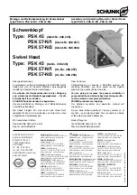
Montage- und Betriebsanleitung für Schwenkkopf
Type PSK 45, PSK 57-N/1, PSK 57-N/2

Assembly and Operating Manual for Swivel Head
Type PSK 45, PSK 57-N/1, PSK 57-N/2

0.8

92

10

R 4

R

2.5

93

100

4 x 90

°

1

Ø 51.5

Ø 56.5

Ø 61

Ø 10

11

Ø 6

30°

R 3

R 3

R 1

R 0.6

Ø 58.2

+ 0.5

Ø 58.8

Ø 57

+ 0.05

1.5

± 0.5

Ø 56.94

+ 0.03

Ø 77

Ø 51

Ø1

0

0.8

0.8

25

45

0.8

7.6

1 x 45°

1 x 45°

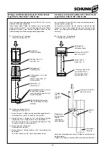
Montagekegel (Werkstoff: Aluminium poliert) /
Mounting taper (Material: polished aluminum)

Spreizhülse (Werkstoff: Delrin oder Nylon) /
Expansion sleeve (Material: Delrin or Nylon)

Kalibrierhülse (Werkstoff: Aluminium poliert) /
Calibration sleeve (Material: polished aluminum)

Fixierbolzen (Werkstoff: 16 Mn Cr 5) /
Fixing pin (Material: 16 Mn Cr 5)

Bolzen (Werkstoff: Aluminium poliert) /
Bolt (Material: polished aluminum)

11.

Montagevorrichtungen

11.

Mounting devices

Ø 57

Ø 40

Ø 62

– 0.060

– 0.070

Rändel / Knurled RGE 1  DIN 82

R max 0.4

180

145

2x3

0

°

1x

45°

1x

45°

Summary of Contents for PSK 45

Page 1: ...SCHUNK Intec N V S A Tel 32 53 853504 Fax 32 53 836022 info be schunk com www be schunk com CANADA SCHUNK Intec Corp Tel 1 905 712 2200 Fax 1 905 712 2210 info ca schunk com www ca schunk com CHINA SC...

Page 2: ...necting diagram for 4 fold distributors 6 8 Schwenkwinkeleinstellung Adjusting the swivel angle 7 9 Problemanalyse Trouble shooting 7 10 Wartung und Pflege Maintenance and care 7 10 1 Zerlegen der Sch...

Page 3: ...modules protective covers must be used according to EC Machine Directive Point 1 4 1 Sicherheit 1 1 Symbolerkl rung Dieses Symbol ist berall dort zu finden wo besondere Gefahren f r Personen oder Bes...

Page 4: ...fahren durch herabfallende und herausgeschleuderte Gegenst nde Es m ssen Vorkehrungen getroffen werden um das Herabfallen oder das Herausschleudern von eventuell gef hrlichen Gegenst nden bearbeitete...

Page 5: ...18H7 und die Zentrierh lsen Pos 28 aus dem Beipack vor gesehen Verwenden Sie beim PSK 57 N zus tzlich die Unterlegscheiben Pos 53 3 Scope of delivery Swivel Head PSK 45 PSK 57 N 1 oder PSK 57 N 2 with...

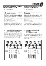
Page 6: ...connection CAUTION During connection the power supply must be swit ched off Please observe the safety instructions on pages 3 and 4 The air connections for the swivel movement are equipped with one w...

Page 7: ...omplette Dichtsatz ist bei Schunk erh ltlich 4 Soweit nicht anderst vorgeschrieben sind alle Schrauben und Muttern mit einem Anzugsmoment gem DIN anzuziehen und mit Loctide Nr 243 oder Gleichwertigem...

Page 8: ...Anfang dieses Kapitels und die Kapitel 10 2 und 10 3 ACHTUNG Besch digen Sie beim Zusammenbau keine Kabel und Dichtungen F r die Montage der Kolben und Dichtungen sind beim Schwenkkopf PSK 57 N Montag...

Page 9: ...nd 93 4 Assembly is done in reverse order Assembly and Disassembly for PSK 57 N For Pos No see chapter 12 Drawings and illustration below 1 Remove the cover Pos 3 or 37 2 Remove the safety ring Pos 86...

Page 10: ...pin the 2nd piston may be used without seal Spreizh lse Expansion sleeve Dichtung Pos 40 Seal Pos 40 Montagekegel Assembly taper 2 O Ringe Pos 41 in Nut einlegenl Insert 2 O rings Pos 41 into the gro...

Page 11: ...1x45 Montagekegel Werkstoff Aluminium poliert Mounting taper Material polished aluminum Spreizh lse Werkstoff Delrin oder Nylon Expansion sleeve Material Delrin or Nylon Kalibrierh lse Werkstoff Alum...

Page 12: ...n 12 Drawings N herungsschalter Proximity switch auf besondere Bestellung upon separate order 66 10 49 1 36 85 45 46 88 37 3 23 30 46 42 80 97 81 4 5 72 56 81 59 62 11 88 17 68 68 54 20 28 65 20 22 71...

Page 13: ...er 66 10 49 1 36 85 45 46 81 37 3 23 30 40 72 62 62 81 4 5 40 42 59 59 59 80 97 81 41 56 11 88 68 53 68 17 54 20 65 28 20 22 71 39 75 19 69 84 71 69 87 51 88 49 86 66 81 61 61 67 35 50 15 83 27 52 88...

Page 14: ...11 032 O Ring O ring DIN 3771 NBR 82 27 x 1 78 1 46 9611 058 O Ring O ring DIN 3771 NBR 60 00 x 2 0 4 49 9611 081 O Ring O ring DIN 3771 NBR 6 00 x 1 5 4 50 9611 016 O Ring O ring DIN 3771 NBR 25 12 x...

Page 15: ...2 45 9611 032 O Ring O ring DIN 3771 NBR 82 27 x 1 78 1 46 9611 025 O Ring O ring DIN 3771 NBR 47 35 x 1 78 4 49 9611 063 O Ring O ring DIN 3771 NBR 6 00 x 1 0 4 50 9611 016 O Ring O ring DIN 3771 NB...

Page 16: ...Ring O ring DIN 3771 NBR 4 00 x 1 5 8 54 9611 519 O Ring O ring DIN 3771 NBR 11 00 x 2 0 8 56 9612 636 Dichtung Seal GM 2000 M 12 2 58 9938 995 O Ring O ring DIN 3771 NBR 122 00 x 2 0 1 59 9660 073 S...

Page 17: ...ng DIN 3771 NBR 25 12 x 1 78 9 52 9611 112 O Ring O ring DIN 3771 NBR 4 00 x 1 5 8 54 9611 519 O Ring O ring DIN 3771 NBR 11 00 x 2 0 8 56 9612 636 Dichtung Seal GM 2000 M 12 2 59 9660 073 Schrauben S...

Page 18: ...cable diameter Do not allow the sensor to make contact with a detectable object of a hard substance or to chemicals especially nitric acid chromic acid and sulfure acid The proximity switches used ar...

Page 19: ...Verstellung m ssen die Gewindestifte Pos 10 erneut mit einem geeigneten Klebstoff gesichert werden Mounting of proximity switches For Pos No see chapter 12 Assembly CAUTION For every assembly work the...

Reviews: