background image

Maintenance

22

03.00 | PWG-S | Assembly and operating manual | en | 389361

6.4 Disassembling the module

Position of the item numbers 

Assembly drawing

 [

}

 24]

 WARNING

Risk of injury due to unexpected movements!

If the power supply is switched on or residual energy remains in
the system, components can move unexpectedly and cause
serious injuries.

Before starting any work on the product: Switch off the power
supply and secure against restarting.

Make sure, that no residual energy remains in the system.

Ø

Remove the compressed air line.

Ø

Loosen the set-screws (12).

Ø

Push out both bolts (6).

Ø

Pull out the fingers (4) and compensation disks from the side of
the body.

Ø

Connect the pressure line to the CLOSED connection and apply
air pressure of 6 bar to the gripper.

Ø

Unscrew the countersunk screw (11) and remove the bar (5).

Ø

Depressurize the gripper and remove the pressure line.

 WARNING

The body (1) is under spring tension.
Risk of injury due to spring forces!

Strictly adhere to the following instructions. 

Carefully

disassemble the module.

Ø

Clamp the body (1) and cylinder (2) between "a" and "b".

Ø

Remove the screws (10).

Ø

Unclamp slowly until the springs are no longer under tension.

Ø

Remove the body (1).

Ø

Pull the piston (3) out of the cylinder (2)

Ø

Remove all seals according to the sealing kit list.

6.5 Servicing and assembling the module

Position of the item numbers 

Assembly drawing

 [

}

 24]

 WARNING

Risk of injury due to spring forces!

The cover is under spring tension.

Carefully disassemble the product.
Summary of Contents for PWG-S 40

Page 1: ...Original operating manual Assembly and operating manual PWG S 2 finger angular gripper...

Page 2: ...ations for the purpose of technical improvement Document number 389361 Version 03 00 26 04 2019 en SCHUNK GmbH Co KG All rights reserved Dear Customer thank you for trusting our products and our famil...

Page 3: ...ating conditions 8 2 7 Personnel qualification 8 2 8 Personal protective equipment 9 2 9 Notes on safe operation 9 2 10 Transport 9 2 11 Malfunctions 10 2 12 Disposal 10 2 13 Fundamental dangers 10 2...

Page 4: ...enance interval 21 6 3 Lubricants Lubrication points basic lubrication 21 6 4 Disassembling the module 22 6 5 Servicing and assembling the module 22 6 5 1 Assembly with assembly bolt 23 6 6 Assembly d...

Page 5: ...esign In addition to these instructions the documents listed under Applicable documents 5 are applicable 1 1 1 Presentation of Warning Labels To make risks clear the following signal words and symbols...

Page 6: ...ealing kit Content of the accessory pack 2 x O ring for hose free direct connection 1x cylindrical pin PWG S 80 2 x locking screw for hose connections ID No of the accessory pack Accessory pack for ID...

Page 7: ...or industrial and industry oriented use Appropriate use of the product includes compliance with all instructions in this manual 2 2 Not intended use It is not intended use if the product is used for e...

Page 8: ...t may be serious injuries and significant property damage All work may only be performed by qualified personnel Before working with the product the personnel must have read and understood the complete...

Page 9: ...handling of the personnel Incorrect handling and assembly may impair the product s safety and cause serious injuries and considerable material damage Avoid any manner of working that may interfere wit...

Page 10: ...per disposal 2 13 Fundamental dangers General Observe safety distances Never deactivate safety devices Before commissioning the product take appropriate protective measures to secure the danger zone D...

Page 11: ...y remains and secure against inadvertent reactivation Never rely solely on the response of the monitoring function to avert danger Until the installed monitors become effective it must be assumed that...

Page 12: ...e measures to secure the danger zone WARNING Risk of injury due to unexpected movements If the power supply is switched on or residual energy remains in the system components can move unexpectedly and...

Page 13: ...Pressure medium Compressed air compressed air quality according to ISO 8573 1 7 4 4 Nominal working pressure bar 6 Min pressure bar 4 Max pressure bar 8 Ambient temperature C Min Max 10 C 90 C Noise e...

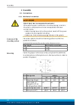
Page 14: ...no residual energy remains in the system Evenness of the mounting surface The values apply to the whole mounting surface to which the product is mounted Requirements for evenness of the mounting surf...

Page 15: ...is exceeded the gripper can be damaged A jaw movement always has to be without jerks and bounce You must therefore implement sufficient reduction and or damping Observe the diagrams and information i...

Page 16: ...S 40 60 80 1 Main connections Hose connection A open B close M5 M5 R1 8 2 M5 M5 R1 8 3 Hose free direct connection at the base a open b close M5 M5 M5 4 M5 M5 M5 Only open the air connections require...

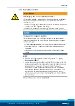
Page 17: ...ipped with reverse polarity protection and are short circuit proof Make sure that you handle the proximity switches properly Do not pull on the cable Do not allow the sensor to dangle from the cable D...

Page 18: ...o sources of high frequency interference and their supply cables Parallel switching of several sensor outputs of the same type npn pnp is permissible but does not increase the permissible load current...

Page 19: ...achment screw 3 open Carefully push the proximity switch 1 into the bracket until it touches the control cam Pull back the proximity switch approx 0 5 mm Fasten the proximity switch by tightening the...

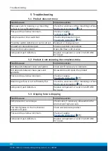
Page 20: ...r repair 5 2 Product is not executing the complete stroke Possible cause Corrective action Dirt deposits between cover and piston Clean and if necessary re lubricate Dirt deposits between basic jaws a...

Page 21: ...ption for the disassembly of the PWG S Disassembling the module 22 Drawing for the construction of the device Assembly drawing 24 RM assembly drawings Assembly drawing 24 6 2 Maintenance interval NOTI...

Page 22: ...ide of the body Connect the pressure line to the CLOSED connection and apply air pressure of 6 bar to the gripper Unscrew the countersunk screw 11 and remove the bar 5 Depressurize the gripper and rem...

Page 23: ...Assembly Assembly takes place in the opposite order to disassembly Observe the following An assembly bolt is required for the assembly of the PGW S 80 Assembly with assembly bolt 23 Unless otherwise s...

Page 24: ...embly drawing The following figure is an example image It serves for illustration and assignment of the spare parts Variations are possible depending on size and variant Wearing part replace during ma...

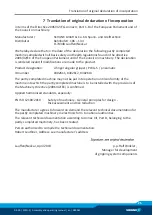
Page 25: ...ger angular gripper PWG S pneumatic ID number 0302611 0302612 0302613 The partly completed machine may not be put into operation until conformity of the machine into which the partly completed machine...

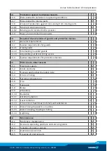
Page 26: ...itions X 1 1 2 Principles of safety integration X 1 1 3 Materials and products X 1 1 4 Lighting X 1 1 5 Design of machinery to facilitate its handling X 1 1 6 Ergonomics X 1 1 7 Operating positions X...

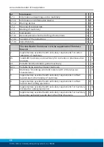
Page 27: ...ble guards X 1 4 2 3 Adjustable guards restricting access X 1 4 3 Special requirements for protective devices X 1 5 Risks due to other hazards 1 5 1 Electricity supply X 1 5 2 Static electricity X 1 5...

Page 28: ...uirements for certain categories of machinery X 2 1 Foodstuffs machinery and machinery for cosmetics or pharmaceutical products X 2 2 Portable hand held and or guided machinery X 2 2 1 Portable fixing...

Reviews: