background image

Basic safety notes

10

06.00 | PZH-plus | Assembly and Operating Manual | en | 389504

The following personal qualifications are necessary for the various
activities related to the product:

Trained electrician

Due to their technical training, knowledge and experience, trained
electricians are able to work on electrical systems, recognize and
avoid possible dangers and know the relevant standards and
regulations.

Qualified personnel

Due to its technical training, knowledge and experience, qualified
personnel is able to perform the delegated tasks, recognize and
avoid possible dangers and knows the relevant standards and
regulations.

Instructed person

Instructed persons were instructed by the operator about the
delegated tasks and possible dangers due to improper behaviour.

Service personnel of
the manufacturer

Due to its technical training, knowledge and experience, service
personnel of the manufacturer is able to perform the delegated
tasks and to recognize and avoid possible dangers.

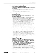
2.7 Personal protective equipment

Use of personal protective equipment

Personal protective equipment serves to protect staff against
danger which may interfere with their health or safety at work.
• When working on and with the product, observe the

occupational health and safety regulations and wear the
required personal protective equipment.

• Observe the valid safety and accident prevention regulations.
• Wear protective gloves to guard against sharp edges and

corners or rough surfaces.

• Wear heat-resistant protective gloves when handling hot

surfaces.

• Wear protective gloves and safety goggles when handling

hazardous substances.

• Wear close-fitting protective clothing and also wear long hair in

a hairnet when dealing with moving components.

Summary of Contents for PZH-plus

Page 1: ...Original operating manual Assembly and Operating Manual PZH plus 3 finger centric gripper ...

Page 2: ...sion 06 00 10 08 2022 en Dear Customer thank you for trusting our products and our family owned company the leading technology supplier of robots and production machines Our team is always available to answer any questions on this product and other solutions Ask us questions and challenge us We will find a solution Best regards Your SCHUNK team Customer Management Tel 49 7133 103 2503 Fax 49 7133 ...

Page 3: ...cation 9 2 7 Personal protective equipment 10 2 8 Notes on safe operation 11 2 9 Transport 11 2 10 Malfunctions 11 2 11 Disposal 12 2 12 Fundamental dangers 12 2 12 1 Protection during handling and assembly 12 2 12 2 Protection during commissioning and operation 13 2 12 3 Protection against dangerous movements 13 2 12 4 Protection against electric shock 13 2 13 Notes on particular risks 14 3 Techn...

Page 4: ...ot achieve the opening and closing times 34 7 Maintenance 35 7 1 Notes 35 7 2 Maintenance and lubrication intervals 35 7 3 Lubricants Lubrication points 35 7 4 Disassembly of the module 36 7 4 1 Assembly tool X 37 7 4 2 Assembly tool Y 38 7 5 Servicing and assembling the module 39 7 5 1 Screw tightening torques 39 7 6 Assembly drawing 39 8 Translation of original declaration of incorporation 41 9 ...

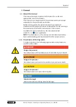
Page 5: ...ts listed under 1 1 2 6 are applicable NOTE The illustrations in this manual are intended to provide a basic understanding and may deviate from the actual version 1 1 1 Presentation of Warning Labels To make risks clear the following signal words and symbols are used for safety notes DANGER Danger for persons Non observance will inevitably cause irreversible injury or death WARNING Dangers for per...

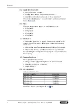
Page 6: ...d the warranty is valid for 36 months from the ex works delivery date under the following conditions Observe the specified maintenance and lubrication intervals Observe the ambient conditions and operating conditions Parts touching the workpiece and wear parts are not included in the warranty 1 3 Scope of delivery The scope of delivery includes 3 finger centric gripper PZH plus in the version orde...

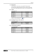
Page 7: ...ID number PZH plus 20 5522219 PZH plus 30 5522220 PZH plus 50 5522221 PZH plus 75 5522222 Contents of the sealing kit 7 6 39 1 4 2 Mounting kit for proximity switch IN ID no of the mounting kit Mounting kit for ID number PZH plus 0305364 1 4 3 Pressure piece assembly kit ID no of the assembly kit Assembly kit for ID number PZH plus 20 0305363 PZH plus 30 0305373 PZH plus 50 0305383 PZH plus 75 030...

Page 8: ...ir The product can be used within the permissible load limits and technical data for holding workpieces during simple machining operations but is not a clamping device according to EN 1550 1997 A1 2008 Appropriate use of the product includes compliance with all instructions in this manual Any utilization that exceeds or differs from the appropriate use is regarded as misuse 2 2 Constructional chan...

Page 9: ...ficant reduction to the product s life span Make sure that the product is used only in the context of its defined application parameters 3 16 Make sure that the product is a sufficient size for the application Make sure that the environment is free from splash water and vapors as well as from abrasion or processing dust Exceptions are products that are designed especially for contaminated environm...

Page 10: ...aviour Service personnel of the manufacturer Due to its technical training knowledge and experience service personnel of the manufacturer is able to perform the delegated tasks and to recognize and avoid possible dangers 2 7 Personal protective equipment Use of personal protective equipment Personal protective equipment serves to protect staff against danger which may interfere with their health o...

Page 11: ...ing the product s application field 2 9 Transport Handling during transport Incorrect handling during transport may impair the product s safety and cause serious injuries and considerable material damage When handling heavy weights use lifting equipment to lift the product and transport it by appropriate means Secure the product against falling during transportation and handling Stand clear of sus...

Page 12: ... the system If the energy supply is connected do not move any parts by hand Do not reach into the open mechanism or movement area of the product during operation 2 12 1 Protection during handling and assembly Incorrect handling and assembly Incorrect handling and assembly may impair the product s safety and cause serious injuries and considerable material damage Have all work carried out by approp...

Page 13: ...he machine must be restricted Limit prevent accidental access for people in this area due through technical safety measures The protective cover and protective fence must be rigid enough to withstand the maximum possible movement energy EMERGENCY STOP switches must be easily and quickly accessible Before starting up the machine or automated system check that the EMERGENCY STOP system is working Pr...

Page 14: ... secure the danger zone WARNING Risk of injury due to unexpected movements If the power supply is switched on or residual energy remains in the system components can move unexpectedly and cause serious injuries Before starting any work on the product Switch off the power supply and secure against restarting Make sure that no residual energy remains in the system WARNING Risk of injury from crushin...

Page 15: ...product cautiously Make sure that no residual energy remains in the system WARNING Risk of injury from objects falling during energy supply failure Products with a mechanical gripping force maintenance can during energy supply failure still move independently in the direction specified by the mechanical gripping force maintenance Secure the end positions of the product with SCHUNK SDV P pressure m...

Page 16: ...re medium Compressed air compressed air quality according to ISO 8573 1 7 4 4 Nominal working pressure bar 6 Min pressure bar 2 Max pressure bar 8 Pressure range for air purge bar 0 5 1 Noise emission dB A 70 More technical data is included in the catalog data sheet Whichever is the latest version ...

Page 17: ...finger centric gripper 1 Housing 2 Air purge connection 3 Main air connections 4 Base jaws 4 2 Description Universal centric gripper with high gripping force and maximum moments due to multi tooth guidance 17 06 00 PZH plus Assembly and Operating Manual en 389504 ...

Page 18: ...roduct is mounted Requirements for evenness of the mounting surface Dimensions in mm Edge length Permissible unevenness 100 0 02 100 0 05 WARNING Risk of injury if the unit falls during transport or assembly Handling with large weight for PZH plus 75 Secure the unit during transport and assembly by sufficiently large aids The gripper is to be hoisted by the three transport threads Eye bolts in the...

Page 19: ...p M6 11 deep M10 17 deep 5 1 1 1 Mounting of the gripper by using a spring loaded pressure piece CAUTION The spring loaded pressure piece is under spring tension The pressure piece can fly out in an uncontrolled fashion and cause contusions During assembly or disassembly be especially careful with the springs When mounting the gripper from the side of the gripper fingers the assembly of the pressu...

Page 20: ...eduction and or damping Observe the information in the catalog data sheet NOTE Observe the requirements for the compressed air supply 3 16 In case of compressed air loss cutting off the energy line the components lose their dynamic effects and do not remain in a secure position However the use of a SDV P pressure maintenance valve is recommended in this case in order to maintain the dynamic effect...

Page 21: ...rge Only open the air connections required For hose free direct connections use the O rings from the accessory pack If the maximum permitted finger weight is exceeded a reduction is imperative so that the jaw movement occurs without any hitting or bouncing Further information on the hose free direct connection contains the catalog data sheet 21 06 00 PZH plus Assembly and Operating Manual en 38950...

Page 22: ...s see Assembly and Operating Manual and catalog data sheet The Assembly and Operating Manual and catalog data sheet are included in the scope of delivery for the sensors and are available at schunk com Information on handling sensors is available at schunk com or from SCHUNK contact persons 5 2 1 Overview of sensors Designation PZH plus 20 30 50 75 Inductive proximity switch IN 80 x x x x Magnetic...

Page 23: ...cid and sulphuric acid The inductive proximity switches are electronic components which can react sensitively to high frequency interference or electromagnetic fields Check to make sure that the cable is fastened and installed correctly Provide for sufficient clearance to sources of high frequency interference and their supply cables Parallel switching of several sensor outputs of the same type np...

Page 24: ... moved in the gripper slot 7 3 Screw in and tighten the screw 5 in the base jaw 6 4 Put the gripper in the position to be monitored opened closed part grasped 5 Position the bracket 2 in such a way that the gripper slot 7 is aligned with the position of the screw 5 6 Insert the proximity switch 1 in the bracket 2 and push it as close as possible to the screw 5 7 Fasten the proximity switch 1 by ti...

Page 25: ...he maximal tightening torque NOTE Ferromagnetic material changes the switching positions of the sensor For example Adapter plate made of ordinary steel At ferromagnetic adapter plates First mount the product on the adapter plate Then set the position of the magnetic switch 25 06 00 PZH plus Assembly and Operating Manual en 389504 ...

Page 26: ...back again slowly until it switches 4 Tighten the set screw 3 to clamp the magnetic switch 1 1 in this position in the groove 5 Close and close the gripper to test its function Gripper closed 1 Set the gripper to the Closed position 2 Push the magnetic switch 2 2 into the groove towards the middle of the gripper until it switches 3 Tighten the set screw 3 to clamp the magnetic switch 2 2 in this p...

Page 27: ... Open and close the gripper to test its function Part gripped I D gripping 1 Clamp the part to be gripped 2 Push the magnetic switch 1 1 into the groove until it stops at the end of the groove 3 Pull the magnetic switch 1 1 back again slowly until it switches 4 Tighten the set screw 3 to clamp the magnetic switch 1 1 in this position in the groove 5 Close and close the gripper to test its function...

Page 28: ...r sensor elements 5 LED display 3 LED display 6 Ribs for cable tires brown white black blue Connection diagram PNP 4 conductor MMS P 22 Types available for order see catalog MMS P 22 S M8 PNP MMSK P 22 S PNP V2 M8 4 2XM8 3 The MMSK P 22 S PNP features a cable with open strands so that it can be connected via terminal contacts The V2 M8 4 2XM8 3 distributor is used to convert the 4 pin connector pl...

Page 29: ...magnetic adapter plates The module must be first mounted on the adapter plate Then the position of the magnetic switchs has to be set 1 To relieve the cable the electronics have to be fixed in place using cable ties 7 There are ribs 6 in place on the electronics for mounting purposes 2 Turn in the sensor 1 4 OR Push the sensor axially into the slot until it contacts the stop 5 3 Fix the sensor wit...

Page 30: ...h in accordance with dimension l2 outer edge of gripper up to the front side of the sensor or in accordance with dimension l1 outer edge of gripper up to the double arrow on the sensor and then mount with a Allen key Dimensions I1 I2 Size l1 mm l2 mm PZH plus 20 49 1 58 0 PZH plus 30 62 8 71 7 ...

Page 31: ...atic mode The trigging point is closer to the switching point At the same time the susceptibility to trouble and damage increases In the mode of the lowest hysteresis an error signal such as jitter or untimely switch off can be avoided if the sensor is protected against all types of disturbances i e by shielding Frequent types of disturbances are change in temperature and electro magnetic influenc...

Page 32: ...ke per jaw X 5 mm to X 10 mm 20 of the nominal stroke per jaw X 10 mm 10 of the nominal stroke per jaw Example Product with 7 mm nominal stroke per jaw 7 mm 20 1 4 mm 1 Press the Teach button 4 for 5 seconds LED 1 3 flashes from 2nd to 5th second LED 1 goes off after 5 sec 2 Release the Teach button 3 Move the gripper to the switch off point for switching point 1 position 4 Briefly press the Teach...

Page 33: ... entire stroke Possible cause Corrective action Dirt deposits between basic jaws and guidance Disassemble and clean the product Pressure drops below minimum Check air supply 5 1 2 20 Mounting surface is not sufficiently flat Check the evenness of the mounting surface 5 1 1 18 Component part defective Send product with a SCHUNK repair order or dismantle product 6 3 Product opens or closes abruptly ...

Page 34: ...trol couplings on the product to the maximum that the movement of the jaws occurs without bouncing and hitting Check compressed air lines Inner diameters of compressed air lines are of sufficient size in relation to compressed air consumption Keep compressed air lines between the product and directional control valve as short as possible Flow rate of valve is sufficiently large relative to the com...

Page 35: ...ardening lubricants Lubricants harden more quickly at temperatures above 60 C leading to possible product damage Reduce the lubricant intervals accordingly Maintenance and lubrication interval Size 20 30 50 75 Interval Mio cycles 5 2 7 3 Lubricants Lubrication points SCHUNK recommends the lubricants listed During maintenance treat all greased areas with lubricant Thinly apply lubricant with a lint...

Page 36: ... power supply and secure against restarting Make sure that no residual energy remains in the system 1 Close the gripper and remove the compressed air lines 2 Remove the cover 15 and unclamp the eccentric 9 To do this rotate the eccentric 9 by 90 to the left Marking has to show in the direction of the outside wall 3 Remove the nuts 61 4 Remove the set screw 45 and undo the screws 46 though the base...

Page 37: ...out the piston rod 5 14 Remove the sleeve 12 15 Remove the air diffuser piece 6 from the housing 1 7 4 1 Assembly tool X Dimensions in mm PZH plus L1 L2 L3 L4 L5 D1 D2 R1 R2 R3 20 113 95 112 0 10 5 10 0 16 0 1 6 8 2 8 0 5 0 1 95 30 111 5 109 0 17 0 10 0 22 0 2 6 12 0 11 0 5 0 2 5 50 107 75 104 0 25 5 13 0 32 0 3 1 17 0 16 0 8 0 3 75 75 123 5 117 5 34 0 15 0 45 0 4 1 21 0 22 5 15 0 6 0 37 06 00 PZH...

Page 38: ...R1 20 100 9 0 4 5 3 0 13 0 17 0 1 0 12 0 12 0 1 6 12 0 M5 30 100 11 5 5 75 5 0 13 0 17 0 1 0 15 0 15 0 2 6 15 0 M5 50 130 15 0 17 0 8 5 8 0 13 0 17 0 1 0 15 0 25 0 2 6 15 0 M5 R8 75 200 15 0 26 0 13 0 8 0 21 0 27 0 1 0 20 0 36 0 5 1 20 0 M8 R8 Assembly tool Y part 2 Dimensions in mm PZH plus L1 L2 D1 D2 D3 20 100 7 12 5 5 10 30 100 7 15 5 5 10 50 100 7 15 5 5 10 75 150 11 20 9 15 ...

Page 39: ... the following Unless otherwise specified secure all screws and nuts with Loctite no 243 and tighten with the appropriate tightening torque 7 5 1 39 7 5 1 Screw tightening torques Position of the item numbers 7 6 39 Values in Nm Item 42 46 47 48 54 56 20 0 8 1 3 0 8 0 8 1 3 1 3 30 1 3 6 0 1 3 1 3 6 0 6 0 50 10 0 6 0 6 0 1 3 10 0 6 0 75 25 0 48 0 25 0 1 3 48 0 10 0 7 6 Assembly drawing The followin...

Page 40: ... Assembly and Operating Manual en 389504 Assembly Wearing part replace during maintenance Included in the seal kit Seal kit can only be ordered completely Positions are adapted to each other and can not be replaced by the customer ...

Page 41: ...305370 0305380 0305390 The partly completed machine may not be put into operation until conformity of the machine into which the partly completed machine is to be installed with the provisions of the Machinery Directive 2006 42 EC is confirmed Applied harmonized standards especially EN ISO 12100 2010 Safety of machinery General principles for design Risk assessment and risk reduction The manufactu...

Page 42: ...les of safety integration X 1 1 3 Materials and products X 1 1 4 Lighting X 1 1 5 Design of machinery to facilitate its handling X 1 1 6 Ergonomics X 1 1 7 Operating positions X 1 1 8 Seating X 1 2 Control Systems 1 2 1 Safety and reliability of control systems X 1 2 2 Control devices X 1 2 3 Starting X 1 2 4 Stopping X 1 2 4 1 Normal stop X 1 2 4 2 Operational stop X 1 2 4 3 Emergency stop X 1 2 ...

Page 43: ... for protective devices X 1 5 Risks due to other hazards 1 5 1 Electricity supply X 1 5 2 Static electricity X 1 5 3 Energy supply other than electricity X 1 5 4 Errors of fitting X 1 5 5 Extreme temperatures X 1 5 6 Fire X 1 5 7 Explosion X 1 5 8 Noise X 1 5 9 Vibrations X 1 5 10 Radiation X 1 5 11 External radiation X 1 5 12 Laser radiation X 1 5 13 Emissions of hazardous materials and substance...

Page 44: ...equirements for certain categories of machinery X 2 1 Foodstuffs machinery and machinery for cosmetics or pharmaceutical products X 2 2 Portable hand held and or guided machinery X 2 2 1 Portable fixing and other impact machinery X 2 3 Machinery for working wood and material with similar physical characteristics X 3 Supplementary essential health and safety requirements to offset hazards due to th...

Page 45: ......

Page 46: ......

Page 47: ......

Page 48: ...ing and gripping technology Bahnhofstr 106 134 D 74348 Lauffen Neckar Tel 49 7133 103 0 Fax 49 7133 103 2399 info de schunk com schunk com Folgen Sie uns I Follow us 08 2022 2022 SCHUNK GmbH Co KG 06 00 PZH plus Assembly and Operating Manual en 389504 ...

Reviews: