background image

Assembly

28

08.00 | PZN-plus | Assembly and Operating Manual | en | 0389374

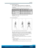
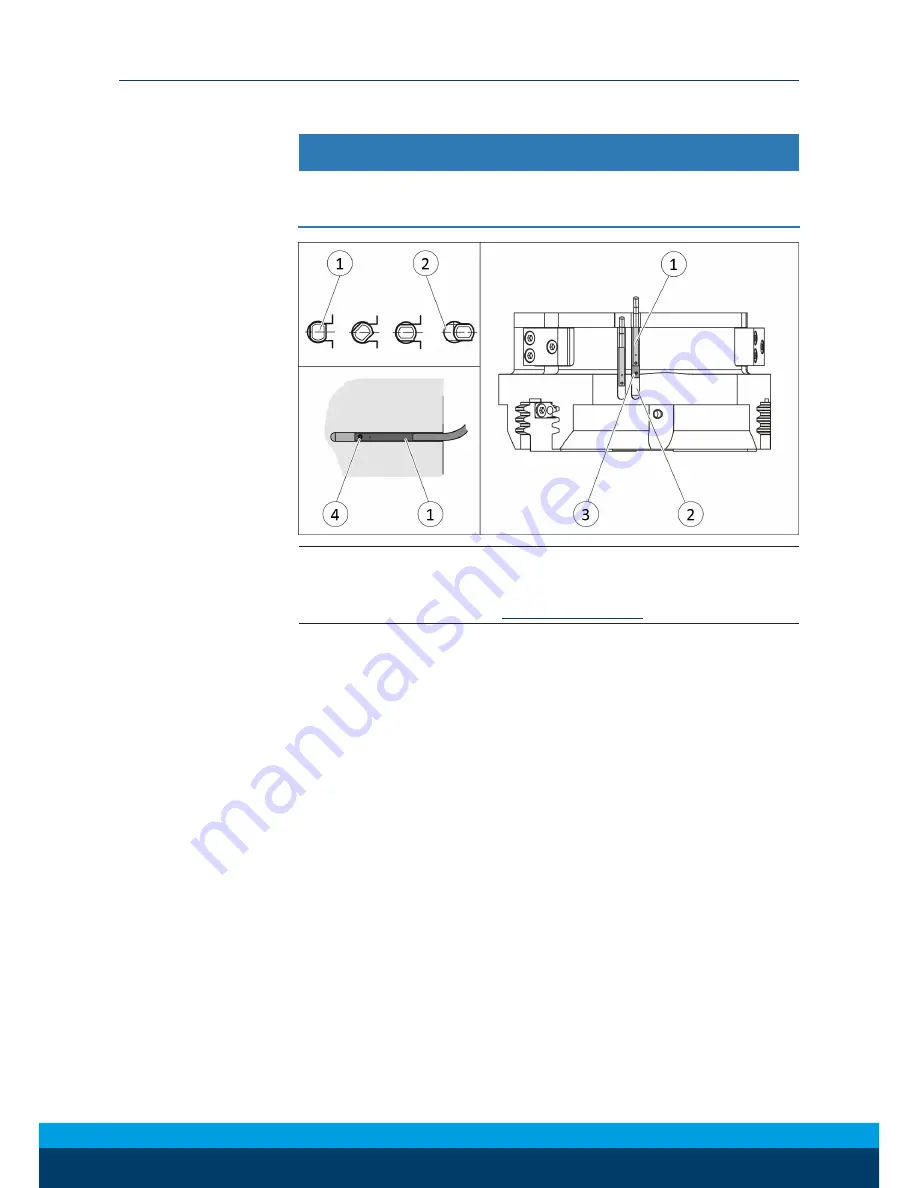
5.3.6 Mounting MMS 22-PI1 programmable magnetic switch

NOTICE

Risk of damage to the sensor during assembly!

Observe the maximal tightening torque.

NOTE

If there is no T-nut available, slide the sensor according to dimen-
sion I1 into the groove (2), 

Setting dimensions

 [

}

 26].

Sizes 40 - 160

Ø

Turn the sensor 1 (1) into the groove (2).
OR: Slide the sensor 1 (1) into the groove (2) until the sensor 1
(1) stops at the T-nut (3).

Ø

Secure the sensor 1 (1) using the set-screw (4).
Tightening torque: 10 Ncm

Ø

Adjust sensor 1 (1), see sensor assembly and operating manual.

Ø

Repeat steps for sensor 2.

Sizes 200 – 380

Ø

Bring gripper in the position in which it is to be set.

Ø

Hold teaching tool to the sensor 1 (1) until the sensor flashes.

Ø

Slide sensor 1 (1) into the groove (2), until the sensor 1 flashes
rapidly.

The optimal position is displayed.

Ø

Secure the sensor 1 (1) using the set-screw (4).
Tightening torque: 10 Ncm

Ø

Hold teaching tool to the sensor 1 (1), to confirm the position.

The sensor 1 (1) has been taught in.

Ø

Repeat steps for sensor 2.

Summary of Contents for PZN-plus 100

Page 1: ...Translation of the original manual Assembly and Operating Manual PZN plus 3 Finger Centric Gripper ...

Page 2: ...terations for the purpose of technical improvement Document number 0389374 Version 08 00 11 01 2018 en SCHUNK GmbH Co KG All rights reserved Dear Customer thank you for trusting our products and our family owned company the leading techno logy supplier of robots and production machines Our team is always available to answer any questions on this product and other solutions Ask us questions and cha...

Page 3: ... 6 Environmental and operating conditions 10 2 7 Personnel qualification 10 2 8 Personal protective equipment 11 2 9 Notes on safe operation 11 2 10 Transport 12 2 11 Malfunctions 12 2 12 Disposal 12 2 13 Fundamental dangers 12 2 13 1 Protection during handling and assembly 13 2 13 2 Protection during commissioning and operation 13 2 13 3 Protection against dangerous movements 14 2 13 4 Protection...

Page 4: ...aw 39 6 Troubleshooting 40 6 1 Product is not moving 40 6 2 Product is not executing the complete stroke 40 6 3 Product opens or closes abruptly 40 6 4 Gripping force is dropping 41 6 5 Product does not achieve the opening and closing times 41 7 Maintenance 42 7 1 Notes 42 7 2 Maintenance intervals 43 7 3 Lubricants greasing areas basic lubrication 44 7 4 Disassembly and assembly 45 7 4 1 Variant ...

Page 5: ... this manual Illustrations in this manual are provided for basic understanding and may differ from the actual product design In addition to these instructions the documents listed under Ap plicable documents 6 are applicable 1 1 1 Presentation of Warning Labels To make risks clear the following signal words and symbols are used for safety notes DANGER Danger for persons Non observance will inevita...

Page 6: ...r homepage schunk com 1 1 3 Sizes This operating manual applies to the following sizes PZN plus 40 PZN plus 50 PZN plus 64 PZN plus 80 PZN plus 100 PZN plus 125 PZN plus 160 PZN plus 200 PZN plus 240 PZN plus 300 PZN plus 380 1 1 4 Variants This operating manual applies to the following variations PZN plus PZN plus with gripping force maintenance O D gripping PZN plus with gripping force maintenan...

Page 7: ... 3 Finger Centric Gripper PZN plus in the version ordered Assembly and Operating Manual Accessory pack 1 3 1 Accessories kit Content of the accessory pack 6 x Centering sleeves for mounting 2 x O ring for hose free direct connection 2 x screw plug for hose connection 2 x Cylindrical pin ID No of the accessory pack Accessory pack for PZN plus PZN plus High temperature HT PZN plus 40 5521694 5521695...

Page 8: ... Dust tight PZN plus Force intensified version KVZ PZN plus 40 5516815 395516815 5518720 PZN plus 50 5516816 395516816 5518721 PZN plus 64 0303450 39303450 5518722 5515869 PZN plus 80 0303451 39303451 5518723 5515870 PZN plus 100 0303452 39303452 5518724 5515871 PZN plus 125 0303453 39303453 5518725 5515872 PZN plus 160 0303454 39303454 5518726 5515873 PZN plus 200 0303455 39303455 5518727 PZN plu...

Page 9: ... for industrial and industry oriented use Appropriate use of the product includes compliance with all in structions in this manual 2 2 Not intended use It is not intended use if the product is used for example as a pressing tool stamping tool lifting gear guide for tools cutting tool clamping device or a drilling tool Any utilization that exceeds or differs from the appropriate use is regarded as ...

Page 10: ...be serious injuries and significant property damage All work may only be performed by qualified personnel Before working with the product the personnel must have read and understood the complete assembly and operating manual Observe the national safety regulations and rules and general safety instructions The following personal qualifications are necessary for the various activities related to the...

Page 11: ...oggles when handling haz ardous substances Wear close fitting protective clothing and also wear long hair in a hairnet when dealing with moving components 2 9 Notes on safe operation Incorrect handling of the personnel Incorrect handling and assembly may impair the product s safety and cause serious injuries and considerable material damage Avoid any manner of working that may interfere with the f...

Page 12: ...ct until the malfunction has been rectified Test the product after a malfunction to establish whether it still functions properly and no increased risks have arisen 2 12 Disposal Handling of disposal The incorrect handling of disposal may impair the product s safety and cause serious injuries as well as considerable material and en vironmental harm Follow local regulations on dispatching product c...

Page 13: ...revention rules Use suitable assembly and transport equipment and take pre cautions to prevent jamming and crushing Incorrect lifting of loads Falling loads may cause serious injuries and even death Stand clear of suspended loads and do not step into their swiv eling range Never move loads without supervision Do not leave suspended loads unattended 2 13 2 Protection during commissioning and operat...

Page 14: ... due through technical safety measures The protective cover and protective fence must be rigid enough to withstand the maximum possible movement energy EMERGENCY STOP switches must be easily and quickly accessible Before starting up the machine or auto mated system check that the EMERGENCY STOP system is working Prevent operation of the machine if this protective equipment does not function correc...

Page 15: ...ctive measures to secure the danger zone WARNING Risk of injury due to unexpected movements If the power supply is switched on or residual energy remains in the system components can move unexpectedly and cause seri ous injuries Before starting any work on the product Switch off the power supply and secure against restarting Ensure that no residual energy remains in the system WARNING Risk of inju...

Page 16: ...e unexpectedly and cause seri ous injuries Disassemble the product cautiously Make sure that no residual energy remains in the system WARNING Risk of injury from objects falling during energy supply failure Products with a mechanical gripping force maintenance can dur ing energy supply failure still move independently in the direc tion specified by the mechanical gripping force maintenance Secure ...

Page 17: ...ping force maintenance Force intensified version KVZ 8 6 5 6 Pressure range for air purge bar 0 5 1 More technical data is included in the catalog data sheet Whichever is the latest version Environmental and operating conditions Designation PZN plus Ambient temperature C min max 5 90 V HT 130 IP protection class 40 SD 64 Noise emission dB A 70 For use in dirty ambient conditions e g sprayed water ...

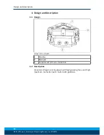
Page 18: ...g Manual en 0389374 4 Design and description 4 1 Design 3 Finger Centric Gripper 1 Housing 2 Base jaw 3 Compressed air main connection 4 2 Description Universal 3 finger centric gripper with high gripping force and high maximum moments due to multi tooth guidance ...

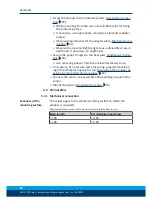
Page 19: ...ermissible finger weight or the permissible mass moment of inertia of the fingers is exceeded the gripper can be damaged A jaw movement always has to be without jerks and bounce You must therefore implement sufficient reduction and or damping Observe the diagrams and information in the catalog data sheet Ø Check the evenness of the mounting surface Mechanical con nection 20 Ø Only open the require...

Page 20: ...per fingers to the base jaws Mechanical connec tion 20 Use centering sleeves from the enclosed accessory pack Ø If necessary fit a pressure piece for spring supported position ing of the workpiece against a stop Mounting of the gripper by using a spring loaded pressure piece 22 Ø Connect the sensor see assembly and operating manual of the sensor Ø Mount the sensor Mounting the sensor 24 5 2 Connec...

Page 21: ...product from the front side A 1 Mounting screw 3 x M3 M3 M5 M6 M6 M8 Mounting the product from the rear side B 2 Mounting screw 3 x M4 M6 M8 M8 M10 Max depth of engagement from locating surface mm without gripping force maintenance 10 13 17 18 21 Max depth of engagement from locating surface mm with gripping force main tenance AS IS 20 5 26 32 38 45 5 3 Fitting bore for cylindrical pins Ø2H7 Ø3H7 ...

Page 22: ...g the gripper fingers 4 Mounting screw 2x M10 M12 M12 M16 M20 Max depth of engagement from locating surface mm 17 17 20 26 30 5 Centering sleeve mm Ø14 Ø16 Ø16 Ø22 Ø28 Contained in accessory pack 5 2 1 1 Mounting of the gripper by using a spring loaded pressure piece CAUTION The spring loaded pressure piece is under spring tension The pressure piece can fly out in an uncontrolled fashion and cause...

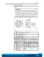
Page 23: ...in the dynamic effect for some time Product variants are also offered with mechanical gripping force via springs which also ensure a minimum clamping force in the event of a pressure drop Air connections 1 Main connections Hose connection A open B close 2 Hose free direct connection a open b close 3 Air purge connection Hose free direct connection 4 Product 5 O ring 6 Attachment Thread diameter of...

Page 24: ... available at schunk com Information on handling sensors is available at schunk com or from SCHUNK contact persons 5 3 1 Overview of sensors Designation PZN plus 40 50 64 80 100 125 160 200 240 300 380 Magnetic switch MMS 22 X X X X X X X X X X X Programmable magnetic switch MMS 22 PI1 X X X X X X X X X X X Programmable magnetic switch MMS 22 PI2 X X X X X X X Programmable magnetic switch MMS P 22...

Page 25: ...0 mm 10 of the nominal stroke per jaw Example Product with 7 mm nominal stroke per jaw 7 mm 20 1 4 mm 5 3 3 Turn control cam Turn control cam example control cam for inductive monitoring Depending on the jaw stroke it may be necessary to change the alignment of the control cam for the sensors IN 80 and RMS 80 In the image the installation situation A shows the control cam in the delivery state of ...

Page 26: ...l1 mm Size l1 mm 40 20 3 80 KVZ 51 9 40 AS 28 2 80 AS KVZ 66 9 40 IS 28 3 80 IS KVZ 66 9 40 KVZ 34 8 100 29 8 40 AS KVZ 42 8 100 AS 49 9 40 IS KVZ 42 8 100 IS 49 8 50 21 7 100 KVZ 59 8 50 AS 32 2 100 AS KVZ 79 8 50 IS 32 1 100 IS KVZ 79 8 50 KVZ 39 7 125 32 5 50 AS KVZ 50 1 125 AS 56 8 50 IS KVZ 50 1 125 IS 57 0 64 24 5 125 KVZ 67 5 64 AS 38 0 125 AS KVZ 92 0 64 IS 38 0 125 IS KVZ 92 0 64 KVZ 45 5...

Page 27: ...of the groove Ø Pull the sensor 1 1 back again slowly until it switches Ø Secure the sensor 1 1 using the set screw 4 Tightening torque 10 Ncm Ø Bring product into the Gripper open or Part gripped position and test the function Position Gripper closed or Part gripped O D gripping Ø Bring product in the position in which it is to be set Ø If necessary remove T nut 3 Ø Turn the sensor 2 1 into the g...

Page 28: ...l the sensor 1 1 stops at the T nut 3 Ø Secure the sensor 1 1 using the set screw 4 Tightening torque 10 Ncm Ø Adjust sensor 1 1 see sensor assembly and operating manual Ø Repeat steps for sensor 2 Sizes 200 380 Ø Bring gripper in the position in which it is to be set Ø Hold teaching tool to the sensor 1 1 until the sensor flashes Ø Slide sensor 1 1 into the groove 2 until the sensor 1 flashes rap...

Page 29: ...aximal tightening torque NOTE If there is no T nut available slide the sensor according to dimen sion I1 into the groove 2 Setting dimensions 26 Ø Turn the sensor 1 into the groove 2 OR Slide the sensor 1 into the groove 2 until the sensor 1 stops at the T nut 3 Ø Secure the sensor 1 using the set screw 4 Tightening torque 10 Ncm Ø Adjust sensor 1 see sensor assembly and operating manual ...

Page 30: ...1 into the groove 2 OR Slide the sensor 1 into the groove 2 until the sensor 1 stops at the T nut 3 Ø Secure the sensor 1 using the set screw 4 Tightening torque 10 Ncm Ø Adjust sensor 1 see sensor assembly and operating manual 5 3 9 Mounting the reed switch RMS 80 NOTICE Blockade of the gripper after setting or replacing of the switch ing cam The switching cam can be tilt in the guide if it was n...

Page 31: ...e stop into the bracket 2 Ø Tighten the screw 3 on the bracket 2 Tightening torque 0 2 Nm Ø Open gripper or grip part Ø Undo the screw 4 Ø Turn the screw 5 to push the position of the control cam 6 Slide control cam 6 inwards until the sensor 1 1 no longer responds Move the control cam 6 back towards the outside until the sensor 1 1 begins to switch Ø Tighten screw 4 and in doing so press the cont...

Page 32: ... to switch Ø Tighten screw 4 and in doing so press the control cam in the direction of the gripper fingers NOTICE The control cam may tilt in the guide if it has not been tightened properly Switching point is set Ø Bring product into the Gripper closed or Part gripped posi tion and test the function NOTE If the switching position cannot be queried it may be that the alignment of the control cam ha...

Page 33: ...e stop into the bracket 2 Ø Tighten the screw 3 on the bracket 2 Tightening torque 0 2 Nm Ø Open gripper or grip part Ø Undo the screw 4 Ø Turn the screw 5 to push the position of the control cam 6 Slide control cam 6 inwards until the sensor 1 1 no longer responds Move the control cam 6 back towards the outside until the sensor 1 1 begins to switch Ø Tighten screw 4 and in doing so press the cont...

Page 34: ... 1 begins to switch Ø Tighten screw 4 and in doing so press the control cam in the direction of the gripper fingers NOTICE The control cam may tilt in the guide if it has not been tightened properly Switching point is set Ø Bring product into the Gripper closed or Part gripped posi tion and test the function NOTE If the switching position cannot be queried it may be that the alignment of the contr...

Page 35: ...w Ø Slide control cam 7 out of the mounting kit with the recess at the front into the base jaw Ø Screw the control cam 7 to the base jaw using the screw 8 Ø Slide spacer shim 9 into the bracket 2 to the stop Ø Slide the sensor 1 to the stop into the bracket 2 Ø Tighten the screw 3 on the bracket 2 Tightening torque 0 2 Nm Ø Adjust sensor 1 see Translation of Sensor Assembly and Oper ating Manual V...

Page 36: ...e gripper open position Ø Loosen screw 4 and remove control cam 6 for the inductive monitoring from the base jaw Ø Apply adhesive to the top and sides of the control cam 6 from the mounting kit Make sure that there is no adhesive on the bottom of the control cam 6 which comes into contact with the sensor SCHUNK recommends the adhesive Loctite 290 or 638 Ø Slide control cam 6 out of the mounting ki...

Page 37: ...ICE Blockade of the gripper after setting or replacing of the switch ing cam The switching cam can be tilt in the guide if it was not fixed ex actly in the base jaw Apply the switching cam in the direction of the base jaw so that the cam does not contact the housing of the gripper Variant Dust tight Before attaching the sensor remove the sealing bolts from the bracket Before adjusting the control ...

Page 38: ...crew the control cam 6 to the base jaw using the screw 5 Secure the screw 5 with medium strength locking liquid Ø Slide the sensor 1 to the stop into the bracket 2 Ø Tighten the screw 3 on the bracket 2 Tightening torque 0 2 Nm Ø Adjust sensor 1 see Translation of Sensor Assembly and Oper ating Manual Variant Dust tight Screw in set screw into the side cover 5 3 14 Mounting the radio system RSS R1...

Page 39: ...jaw 1 and active force measur ing jaw 3 onto the base jaw 2 Use centering sleeves between force measuring jaw and in termediate jaw Ø Screw gripper fingers onto the force measuring jaws 1 3 Use centering sleeves between force measuring jaw and grip per finger Ø Connect the evaluation unit see the Assembly and Operating Manual for the sensor ...

Page 40: ...t executing the complete stroke Possible cause Corrective action Dirt deposits between cover and piston Clean and if necessary re lubricate Maintenance 42 Dirt deposits between basic jaws and guid ance Disassemble and clean the product Pressure drops below minimum Check air supply Pneumatic connection 23 Mounting surface is not sufficiently flat Check the evenness of the mounting surface Mechanica...

Page 41: ...lly If present Open the flow control couplings on the product to the maximum that the movement of the jaws occurs without boun cing and hitting Check compressed air lines Inner diameters of compressed air lines are of sufficient size in relation to compressed air consumption Keep compressed air lines between the product and directional control valve as short as possible Flow rate of valve is suffi...

Page 42: ...faces wear safety gloves Before carrying out any work make sure that all surfaces have cooled down to the ambient temperature Original spare parts Use only original spare parts of SCHUNK when replacing spare and wear parts Exchange of housing and base jaws The base jaws and the guidance in the housing are matched To ex change these parts send the product with a repair order to SCHUNK or order the ...

Page 43: ...Reduce the lubricant intervals accordingly Interval million cycles for PZN plus Maintenance work 40 160 200 300 380 10 5 0 05 Clean all parts thoroughly check for damage and wear if necessary replace seals and wearing parts Disassembly and assembly 45 The seals are in the enclosed sealing kit Sealing kit 8 10 5 0 05 Treat all grease areas with lubricant Lubricants greasing areas basic lubrica tion...

Page 44: ... 2 PZN plus 40 300 Depending on the load the guides in the housing can be re lubricated PZN plus 380 The lubrication is made via the lubricating nipples on the lubricat ing hole The other lubricating holes must be closed with a grub screw Therefore 15 ml of the lubricant have to be pumped in the gripper using the lubricating nipples After the lubricating process remove the lubricating nipples and ...

Page 45: ... item numbers Drawings 53 WARNING Risk of injury due to unexpected movements If the power supply is switched on or residual energy remains in the system components can move unexpectedly and cause seri ous injuries Before starting any work on the product Switch off the power supply and secure against restarting Ensure that no residual energy remains in the system WARNING In the case of the version ...

Page 46: ...K to disassemble the gripper for the purpose of main tenance and seal replacement WARNING Risk of injury due to spring forces When disassembling the cover and the cylinder piston can be thrown out by high spring forces Secure the cover from being ejected during disassembly e g in a press WARNING Risk of injury due to unexpected movements If the power supply is switched on or residual energy remain...

Page 47: ...ver plate 5 Ø Mark the installation position of the piston 3 and the base jaws 2 in the housing 1 Ø Clamp the gripper with suitable plastic base 101 between the base jaws 2 and the cover 9 in a press 100 so that the 8 screws 46 still can be removed Ø Unscrew the screws 46 Ø Open press 100 carefully Ø Remove the cover 5 Ø Remove centering pins 55 ...

Page 48: ...nd then carefully open the press 100 un til the compression spring is fully extended Ø Remove the cylinder piston 60 and the compression springs 25 from the housing 1 Ø Push the piston 3 upwards and out of the housing 1 Ø Pull the base jaws 2 out of the housing 1 7 4 4 Version with gripping force maintenance I D WARNING Danger due to very high spring forces With regard to size PZN plus 240 300 and...

Page 49: ... unexpected movements If the power supply is switched on or residual energy remains in the system components can move unexpectedly and cause seri ous injuries Before starting any work on the product Switch off the power supply and secure against restarting Ensure that no residual energy remains in the system Ø Remove the compressed air lines Ø Undo the screws 47 and then remove the cover plate 5 Ø...

Page 50: ...ersion with force amplification cylinder KVZ WARNING Danger due to very high spring forces With regard to size PZN plus 240 300 and 380 with gripping force maintenance we urgently recommend that you get SCHUNK to disassemble the gripper for the purpose of main tenance and seal replacement WARNING Risk of injury due to spring forces When disassembling the cover can be thrown out by high spring forc...

Page 51: ... base jaw 2 in the housing 1 Ø Version with gripping force maintenance A D or O D As described in the previous chapters Version with gripping force maintenance O D 46 Version with gripping force mainten ance I D 48 clamp the gripper into a press and remove the screws 54 Version without gripping force maintenance Remove the screws 54 and then remove the cover 4 Ø Unscrew the screw 51 and remove the...

Page 52: ...the housing 1 7 4 6 Notes for assembly Assembly takes place in the opposite order to disassembly Ob serve the following Unless otherwise specified secure all screws and nuts with Loc tite no 243 and tighten with the appropriate tightening torque Screw tightening torques 53 For variant with gripping force maintenance assemble cylinder piston using a press Version without gripping force mainten ance...

Page 53: ...2 12 20 49 96 7 4 8 Spring force information for assembly Size 40 50 64 80 100 125 160 200 240 300 380 with gripping force maintenance O D gripping preload mm 14 6 15 27 24 29 47 55 25 90 47 spring force N 174 132 261 496 875 1253 2372 4982 5016 9465 1013 0 with gripping force maintenance I D gripping preload mm 10 14 46 36 46 71 96 100 48 100 63 spring force N 111 183 388 701 1389 2037 3927 7373 ...

Page 54: ... variants O D gripping I D gripping without gripping force maintenance 1 Wearing part replace during maintenance Included in the seal kit Seal kit can only be ordered completely 2 Positions are adapted to each other and can not be replaced by the customer 3 not for PZN plus 40 125 4 from size PZN plus 125 ...

Page 55: ...Maintenance 08 00 PZN plus Assembly and Operating Manual en 0389374 55 7 5 2 Variant with dust cover ...

Page 56: ...ng Manual en 0389374 7 5 3 Variant with force amplification cylinder 1 Wearing part replace during maintenance Included in the seal kit Seal kit can only be ordered com pletely 2 not for PZN plus 64 125 3 from size PZN plus 125 4 from size PZN plus 160 ...

Page 57: ...3 Finger Centric Gripper PZN plus pneumatic ID number 0303308 0303648 The partly completed machine may not be put into operation until conformity of the ma chine into which the partly completed machine is to be installed with the provisions of the Machinery Directive 2006 42 EC is confirmed Applied harmonized standards especially EN ISO 12100 2010 Safety of machinery General principles for design ...

Page 58: ...equirements 1 1 1 Definitions X 1 1 2 Principles of safety integration X 1 1 3 Materials and products X 1 1 4 Lighting X 1 1 5 Design of machinery to facilitate its handling X 1 1 6 Ergonomics X 1 1 7 Operating positions X 1 1 8 Seating X 1 2 Control Systems 1 2 1 Safety and reliability of control systems X 1 2 2 Control devices X 1 2 3 Starting X 1 2 4 Stopping X 1 2 4 1 Normal stop X 1 2 4 2 Ope...

Page 59: ...1 4 2 2 Interlocking movable guards X 1 4 2 3 Adjustable guards restricting access X 1 4 3 Special requirements for protective devices X 1 5 Risks due to other hazards 1 5 1 Electricity supply X 1 5 2 Static electricity X 1 5 3 Energy supply other than electricity X 1 5 4 Errors of fitting X 1 5 5 Extreme temperatures X 1 5 6 Fire X 1 5 7 Explosion X 1 5 8 Noise X 1 5 9 Vibrations X 1 5 10 Radiati...

Page 60: ...equirements for certain categories of machinery X 2 1 Foodstuffs machinery and machinery for cosmetics or pharmaceutical products X 2 2 Portable hand held and or guided machinery X 2 2 1 Portable fixing and other impact machinery X 2 3 Machinery for working wood and material with similar physical charac teristics X 3 Supplementary essential health and safety requirements to offset haz ards due to ...

Reviews: