14
Montage- und Betriebsanleitung
für 3-Finger-Zentrischgreifer Type PZN
Assembly and Operating Manual for
for 3-Finger-Centric Gripper Type PZN
Montage und Einstellung der Näherungsschal-
ter – PZN 64, 80, 100, 125, 160, 200
HINWEIS:
Bei PZN 50 erfolgt die Näherungsschalterabfrage ohne
Schaltnocken.
Die Einstellung der Näherungsschalter bei PZN 50 ist auf Seite
15 beschrieben.
Die Schaltnocken für Greifer »Auf« und »Zu« sind montiert und
eingestellt. Die Schaltnocken für Zwischenstellungen
werden im Beipack mitgeliefert.
Für Greiferstellung »Teil gegriffen« befindet sich im Beipack eine
Schaltnocke, die bei zu großer Störkante gekürzt werden kann.
Mounting and adjusting of the proximity-
switches – PZN 64, 80, 100, 125, 160, 200
NOTE:
For PZN 50, interrogation is done without control cam.
The adjustment of the proximity switches is described on
page 15.
The switch cams for gripper ”open“ and ”close“ are already moun-
ted and adjusted. Control cams for intermediate positions can be
found in the little plastic bag.
For gripper position "component gripped" a control cam is nee-
ded, which may be shortened for large interfering edges. This
control cam is supplied free of charge in every consignment of
this type of gripper.
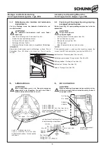
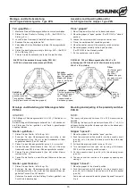
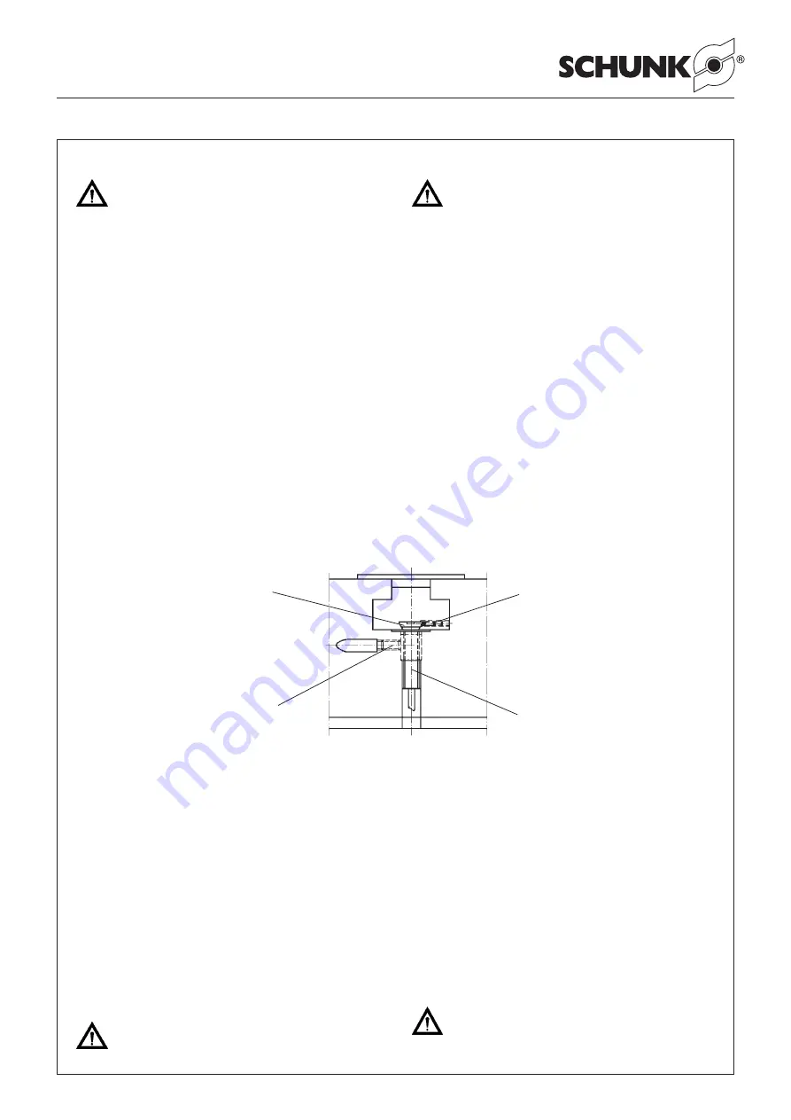
Schaltnocke magnetisch /
Control cam (magnetic)
Klemmschraube, Schaltnocke /
Clamping screw, Control cam
Näherungsschalter /
Proximity switch
Klemmschraube N-Schalter Pos. 23 /
Clamping screw, Proximity switch
ACHTUNG:
Die induktiven Näherungsschalter sind elektronische
Bauteile, welche empfindlich auf hochfrequente
Störungen oder elektromagnetische Felder reagieren
können. Prüfen Sie die Anbringung und Installation
des Kabels. Der Abstand zu hochfrequenten Stör-
quellen und deren Zuleitung muss ausreichend sein.
Das Parallelschalten mehrerer Sensorausgänge der
gleichen Bauart (npn, pnp) ist zwar erlaubt, erhöht
aber nicht den zulässigen Laststrom. Beachten Sie
weiterhin, dass sich der Leckstrom der einzelnen
Sensoren (ca. 2 mA) addiert.
CAUTION:
Proximity switches are electronic parts which are
sensitive to any electromagnetic fields or high-fre-
quency disturbances. Check the position and instal-
lation of the cable. Make sure that you keep a suffi-
ciently large distance to any source of interference. It
is allowed to mount several sensors of the same type
parallel to each other. This construction does not
increase the permitted load. You also have to take
into account that the leakage load of each sensor
(appr. 2 mA) adds up.
Greifer »geöffnet«:
1. Stellen Sie den Greifer in Stellung »Auf«.
2. Schieben Sie den Schließer vorsichtig in die Bohrung, bis der
Schalter die Schaltnocke berührt.
3. Ziehen Sie den Näherungsschalter um ca. 0,5 mm zurück.
4. Fixieren Sie den Näherungsschalter mit dem Gewindestift
(Pos. 23). Bei der gesonderten Halterung (nur PZN 50, 64, 80
und 100) Klemmschraube anziehen.
5. Schließen Sie den Näherungsschalter an.
. Testen Sie die Funktion, indem Sie den Greifer schließen und
öffnen.
Greifer »geschlossen«:
1. Stellen Sie den Greifer in Stellung »Zu«.
Verfahren Sie mit dem Schließer wie von Punkt 2. bis Punkt 6.
beschrieben.
ACHTUNG!
Das maximale Anzugsmoment für die Bestigungs-
schrauben der Näherungsschalter beträgt 100 Ncm.
Gripper ”open“:
1. Move the gripper to the ”open“ position.
2. Actuate the closer carefully into the drill until the switch tou-
ches the control cam.
3. Pull back the proximity switch for appr. 0,5 mm.
4. Fix the proximity switch with the sets crew (pos. 23). For extra
mounting, you have to tighten the clamping screw. (only for
PZN 50, 64, 80 and 100).
5. Connect the proximity switch.
6. Control function by closing and opening the gripper.
Gripper ”closed“
1. Move the gripper to the ”closed“ position.
For the closer, proceed in the same way as it is described from
point 2 to 6.
CAUTION!
The max. tightening moment of the screws of the pro-
ximity switch is 100 Ncm.

