background image

Technical data

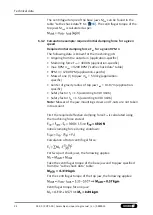
The required effective clamping force for machining F

sp

 is

calculated from the product of the 

machining force F

spZ

 and the

safety factor S

z

. This factor takes into account uncertainties in the

calculation of the machining force. According to VDI 3106: 

S

z

 ≥ 1.5.

From this we can derive the calculation of the initial clamping
force during shutdown:

(+)

 for gripping from the outside inwards

(–)

 for gripping from the inside outwards

CAUTION

This calculated force must not be larger than the maximum
clamping force ΣS engraved on the lathe chuck.

See also "Lathe chuck data" table 

}

 6.1 [

/

 18]

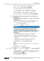
From the above formula it is evident that the sum of the effective
clamping force F

sp

 and the total centrifugal force F

c

 is multiplied by

the 

safety factor for the clamping force S

sp

. According to VDI 3106,

the following also applies here: 

S

sp

 ≥ 1.5.

The 

total centrifugal force F

c

 is dependent on both the sum of the

masses of all jaws and on the center of gravity radius and the
speed of rotation.

CAUTION

For safety reasons, in accordance with DIN EN 1550, the
centrifugal force may be a maximum of 67% of the initial
clamping force.

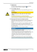
The formula for the calculation of the total centrifugal force F

c

 is:

For this, 

n is the given speed of rotation

 in RPM. The product 

m

B


r

s


is referred to as the centrifugal torque M

c

.

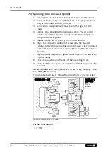
In case of toolholders with split chuck jaws, i.e., with base jaws and
top jaws, for which the base jaws change their radial position only
by the stroke amount, the 

centrifugal torque of the base jaws

M

cGB

 and the 

centrifugal torque of the top jaws M

cAB

 need to be

added:

23

03.00 | ROTA 2B | Assembly and operating manual | en | 0889059

Summary of Contents for ROTA 2B

Page 1: ...Translation of the original manual Power Chuck ROTA 2B Assembly and operating manual ...

Page 2: ...0 09 02 2022 en Dear Customer thank you for trusting our products and our family owned company the leading technology supplier of robots and production machines Our team is always available to answer any questions on this product and other solutions Ask us questions and challenge us We will find a solution Best regards Your SCHUNK team Customer Management Tel 49 7572 7614 1300 Fax 49 7572 7614 103...

Page 3: ...force speed diagrams 19 6 3 Calculations for clamping force and speed 21 6 3 1 Calculation of the required clamping force in case of a given rpm 22 6 3 2 Calculation example required initial clamping force for a given speed 24 6 3 3 Calculation of the permissible speed in case of a given initial clamping force 25 6 4 Grades of Accuracy 26 6 5 Permissible imbalance 26 7 Attachment 27 7 1 Pre assemb...

Page 4: ... 4 Central oil lubrication 35 9 5 Changing the stepped jaws 35 10 Disposal 36 11 Section and exploded drawing 37 12 Spare parts 39 13 Translation of original EC declaration of incorporation 40 14 Appendix on Declaration of Incorporation as per 2006 42 EC Annex II No 1 B 41 4 03 00 ROTA 2B Assembly and operating manual en 0889059 ...

Page 5: ...is manual are provided for basic understanding of the product and may differ from the actual product design We accept no liability for damage resulting from the failure to observe and comply with this operating manual 1 1 Warnings To make risks clear the following signal words and symbols are used for safety notes DANGER Danger for persons Non observance will inevitably cause irreversible injury o...

Page 6: ...bout hot surfaces 1 2 Applicable documents General terms of business Catalog data sheet of the purchased product Calculation of the jaw centrifugal forces Technology chapter in the lathe chuck catalog The documents marked with an asterisk can be downloaded on our homepage schunk com ...

Page 7: ...ad and understood this operating manual in its entirety especially the chapter Basic safety notes The maximum RPM of the chuck and the required clamping force must be determined by the user for the respective clamping task based on the applicable standards and technical specifications of the manufacturer See also Calculations for clamping force and RPM in the chapter Technical data 6 18 2 2 Not in...

Page 8: ...maintain the lathe chuck s clamping force until the machine comes to a standstill and the workpiece can be secured e g using a crane or suitable lifting equipment The machines and equipment must fulfill the minimum requirements of the EC Machinery Directive specifically they must have effective technical measures to protect against potential mechanical hazards DANGER Possible risk of fatal injury ...

Page 9: ...g the chuck Note the relevant load securing regulations for working safely with cranes ground conveyors lifting gear and load handling equipment CAUTION Danger of slipping and falling in case of dirty environment where the chuck is used e g by cooling lubricants or oil Ensure that the working environment is clean before starting assembly and installation work Wear suitable safety shoes Follow the ...

Page 10: ...ed rotating parts and noise generation Physical and mental strains due to imbalanced workpieces and noise during the machining process on the clamped and rotating workpiece Ensure the chuck s axial and concentric runout Check options for remedying imbalances on special top jaws and workpieces Reduce the speed Wear hearing protection 2 4 Notes on safe operation The machine spindle may only be start...

Page 11: ...an the chuck s top speed a reliable speed limiter must be installed and proof must be provided that the speed limiter is effective Maintenance instructions The chuck s reliability and safety can only be guaranteed if the operator complies with the manufacturer s maintenance instructions For lubrication we recommend our tried and tested special grease LINOMAX plus Unsuitable lubricants can have a n...

Page 12: ...articular attention to the operating system and hazard assessment DANGER Possible risk of fatal injury to operating personnel due to toolholder failure if the maintenance and servicing instructions for the toolholder are disregarded The servicing instructions specified by the manufacturer must be complied with to ensure safe operation of the chuck Work must be carried out by qualified specialist p...

Page 13: ...ur chuck must have access to the operating manual especially the chapter Fundamental safety instructions We recommend that the operator create in house safety operating instructions Persons in training may be assigned to machines and technical equipment in which a chuck is mounted only if they are under the constant guidance and supervision of qualified specialists 2 6 Organizational measures Obey...

Page 14: ...ted and remedied Only allow specialists to remedy faults Spare parts Only ever use original SCHUNK spare parts Environmental regulations Comply with the applicable legal norms when disposing of waste 2 7 Using personal protective equipment When using this product you must comply with the relevant health and safety at work rules and you must use the required personal safety equipment minimum catego...

Page 15: ...ions Observe the applicable documents 1 2 6 Observe the ambient conditions and operating conditions Observe the maximum number of clamping cycles 6 18 Observe the specified maintenance and lubrication intervals 9 33 Parts touching the workpiece and wear parts are not included in the warranty 15 03 00 ROTA 2B Assembly and operating manual en 0889059 ...

Page 16: ...other suitable technical equipment screw quality 10 9 Screw size M6 M8 M10 M12 M14 M16 M18 M20 M22 M24 M27 M30 Admissible torque MA Nm 13 28 50 88 120 160 200 290 400 500 1050 1500 Tightening torques for mounting screws used to attach top jaws onto the chuck screw quality 12 9 Screw size M6 M8 M10 M12 M14 M16 M20 M24 Max admissible torque MA Nm 16 30 50 70 130 150 220 450 ...

Page 17: ...ry The scope of delivery includes 2 Jaw Power Chuck incl 4 fastening screws for base jaws with fine serration 4 T nuts with screws for base jaws with slot and tenon 2 screws 12 9 17 03 00 ROTA 2B Assembly and operating manual en 0889059 ...

Page 18: ...s only valid for max operating force and the use of the suitable hard standard stepped jaws WARNING Danger of personal injury and property damage caused by flying parts in case of spiral fracture of soft top jaws Soft standard top jaws must be hardened at the area around the countersink They should only be depth hardened not surfacehardened When using unhardened top jaws or jaws in special design ...

Page 19: ...greased with special SCHUNK grease LINO MAX Chuck set up for gripping force speed diagram F 3 Clamping force per jaw S Centre of gravity rREPLACE MEsREPL ACEME Center of gravity radius aREPLAC EMEma xREPLAC EME Max jaw eccentricity of center of gravity in axial direction FREPLAC EMEma xREPLAC EME Actuating force Clamping force speed diagram ROTA 2B 125 19 03 00 ROTA 2B Assembly and operating manua...

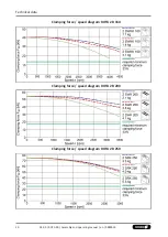
Page 20: ...Technical data 20 03 00 ROTA 2B Assembly and operating manual en 0889059 Clamping force speed diagram ROTA 2B 160 Clamping force speed diagram ROTA 2B 200 Clamping force speed diagram ROTA 2B 250 ...

Page 21: ...m Fsp Effective clamping force N McGB Centrifugal torque of base jaws Kgm Fspmin Minimum required clamping force N n Speed rpm Fsp0 Initial clamping force N rs Center of gravity radius m Fspz Cutting force N rsAB Center of gravity radius of top jaw m mAB Mass of one top jaw kg ssp Safety factor for clamping force mB Mass of chuck jaw set kg sz Safety factor for machining Mc Centrifugal force torqu...

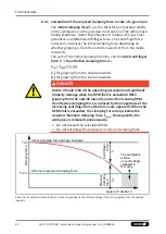
Page 22: ...ing from the inside outwards DANGER Risk to life and limb of the operating personnel and significant property damage when the RPM limit is exceeded With gripping from the outside inwards and with increasing RPM the effective clamping force is reduced by the magnitude of the increasing centrifugal force the forces are opposed When the RPM limit is exceeded the clamping force drops below the require...

Page 23: ...s multiplied by the safety factor for the clamping force Ssp According to VDI 3106 the following also applies here Ssp 1 5 The total centrifugal force Fc is dependent on both the sum of the masses of all jaws and on the center of gravity radius and the speed of rotation CAUTION For safety reasons in accordance with DIN EN 1550 the centrifugal force may be a maximum of 67 of the initial clamping fo...

Page 24: ...k data table RPM n 1200 RPM application specific Mass of one top jaw mAB 5 33 kg application specific Center of gravity radius of top jaw rsAB 0 107 m application specific Safety factor Sz 1 5 according to VDI 3106 Safety factor Ssp 1 5 according to VDI 3106 Note Masses of the jaw mounting screws and T nuts are not taken into account First the required effective clamping force Fsp is calculated us...

Page 25: ...scribed on the lathe chuck Example of calculation Permissible RPM for a given effective clamping force The following data is known from previous calculations Initial clamping force during shutdown Fsp0 17723 N Machining force for machining job Fspz 3000 N application specific Total centrifugal torque of all jaws Mc 2 668 kgm Safety factor Sz 1 5 according to VDI 3106 Safety factor Ssp 1 5 accordin...

Page 26: ...pond to balancing quality class 6 3 according to DIN ISO 21940 11 Residual imbalance risks may arise due to insufficient rotation compensation being achieved see DIN EN 1550 6 2 e This applies in particular to high speeds of rotation asymmetrical workpieces or the use of lathe chucks that do not correspond to balancing grade 6 3 as well as uneven lubricant application In order to prevent damage re...

Page 27: ...out The permissible limit is 0 005 mm as per DIN 6386 and ISO 3089 Completely remove cylinder screws item 15 and the top For actuation of the clamping cylinder please remove the drawbar to its front position Push the chuck piston 3 into its foremost position CAUTION No stop in front of the piston position The adaptation between the drawtube and drawbar of the machine and the chuck piston should be...

Page 28: ...Attachment 28 03 00 ROTA 2B Assembly and operating manual en 0889059 Maximal possible front piston position in which the chuck piston not strikes measure in mm ...

Page 29: ...tre of the spindle in front of the spindle nose Using a socket head screw to tighten screw item 6 on the draw bar to the stop Tighten chuck fastening screws item 21 in turn Assembly the chuck cover item 4 with 4 screws item 20 Check the concentricity and face runout at the control rim Check the function and the size of the operating force Check that the base jaws run smoothly and that the jaw stro...

Page 30: ...on item 3 to the front position 6 align chuck to piston centre and screw onto the Opus B cylinder to the stop by rotating around its own axis Turn chuck back until the countersunk screw overlaps the threads in the Opus B 7 align Opus B if necessary Tighten chuck fastening screws item 21 alternately 8 Check the function and the size of the operating force 9 Check that the base jaws run smoothly and...

Page 31: ...id connecting thread The chucks has to be always mounted by turning around their own axis onto the clamping cylinder The screw piece is secured on the chuck side against twisting and does not additionally be secured 31 03 00 ROTA 2B Assembly and operating manual en 0889059 ...

Page 32: ... slot and tenon only The top jaws are moved or changed with the clamps open ROTA 2B s long jaw stroke makes it particularly suitable for bridging long travel distances from workpiece shapes to clamping position This makes this chuck especially appropriate for fittings and cast components ROTA 2B chucks installation height has been improved shorter 8 2 Replacement or renewal of jaws Clamping jaws f...

Page 33: ... When assembling ensure that the mark on the piston item 3 is aligned with jaw guide 1 engraved in chuck body 5 Turn chuck on its head and pull piston item 3 out of the housing Remove set screw item 29 Unscrew nut from this assembly item 5 The screw can now be taken out Remove ball item 24 and spring item 25 Remove O ring item 36 from screw 6 Turn chuck upwards on to its front Push one base jaw to...

Page 34: ...oo for screws quality class Mounting of the chuck follows in reverse order 9 2 Lubrication To maintain the safe functioning and high quality of the chuck it has to be regularly lubricated according to the maintenance intervals below item 23 Important note The chuck should always be lubricated in the position in which the base jaws are radially outermost This corresponds to the front piston positio...

Page 35: ...gularly appropriate to the application use Lubricating oil VG220 DIN 51519 is applied to the bottom of the chuck into a bore Important note The chuck should always be lubricated in the position in which the base jaws are radially outermost This corresponds to the front piston position As a rule a 3 second 10 to 30 bar pulse should be applied to the chuck 3 6 times an hour Two gauge cartridges ensu...

Page 36: ...o drain out Collect the escaping liquids and dispose of them properly in line with the statutory provisions Remove any identifiable plastic or aluminum parts installed in or on the chuck and dispose of them properly in line with the statutory provisions Dispose of the chuck s metal parts as scrap metal Alternatively you can return the chuck to SCHUNK for proper disposal ...

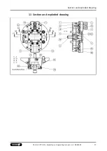
Page 37: ...Section and exploded drawing 11 Section and exploded drawing 37 03 00 ROTA 2B Assembly and operating manual en 0889059 ...

Page 38: ...Section and exploded drawing 38 03 00 ROTA 2B Assembly and operating manual en 0889059 ...

Page 39: ...nting screw 8 Filler 10 Wiper bar left 11 Wiper bar right 15 T nut with screws DIN EN ISO 4762 12 9 or slot and tenon screw DIN EN ISO 4762 10 9 19 Screw DIN EN ISO 4762 10 9 20 Screw DIN EN ISO 4762 10 9 21 Screw DIN EN ISO 4762 10 9 22 Oval head screw 23 Lubricating nipple 24 Pressure spring 25 Steel bar DIN ISO 3290 28 Cylindrical pin DIN EN ISO 8734 29 Set screws DIN 914 30 Set screw DIN EN IS...

Page 40: ...completed machine is to be installed with the provisions of the Machinery Directive 2006 42 EC is confirmed Applied harmonized standards especially DIN EN ISO 12100 2010 Safety of machinery General principles for design Risk assessment and risk reduction DIN EN ISO 1550 1997 A1 2008 Machine tools safety Safety requirements for the design and constructions of workholding chucks Other related techni...

Page 41: ... Not relevant 1 1 Essential Requirements 1 1 1 Definitions X 1 1 2 Principles of safety integration X 1 1 3 Materials and products X 1 1 4 Lighting X 1 1 5 Design of machinery to facilitate its handling X 1 1 6 Ergonomics X 1 1 7 Operating positions X 1 1 8 Seating X 1 2 Control Systems 1 2 1 Safety and reliability of control systems X 1 2 2 Control devices X 1 2 3 Starting X 1 2 4 Stopping X 1 2 ...

Page 42: ...1 Fixed guards X 1 4 2 2 Interlocking movable guards X 1 4 2 3 Adjustable guards restricting access X 1 4 3 Special requirements for protective devices X 1 5 Risks due to other hazards 1 5 1 Electricity supply X 1 5 2 Static electricity X 1 5 3 Energy supply other than electricity X 1 5 4 Errors of fitting X 1 5 5 Extreme temperatures X 1 45 6 Fire X 1 5 7 Explosion X 1 5 8 Noise X 1 5 9 Vibration...

Page 43: ...achinery X 2 1 Foodstuffs machinery and machinery for cosmetics or pharmaceutical products X 2 2 Portable hand held and or guided machinery X 2 2 1 Portable fixing and other impact machinery X 2 3 Machinery for working wood and material with similar physical characteristics X 3 Supplementary essential health and safety requirements to offset hazards due to the mobility of machinery X 4 Supplementa...

Page 44: ...UNK GmbH Co Spanntechnik KG Lothringer Str 23 D 88512 Mengen Tel 49 7572 7614 0 Fax 49 7572 7614 1099 info de schunk com schunk com Folgen Sie uns I Follow us 02 2022 2022 SCHUNK GmbH Co KG 03 00 ROTA 2B Assembly and operating manual en 0889059 ...

Reviews: