Attachment
7 Attachment
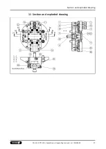
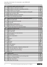
The item numbers specified for the corresponding individual
components relate to chapter drawings.
7.1 Pre-assembly measures
Carefully lift the product (e.g. using suitable lifting gear) from the
packaging.
CAUTION
Danger of injury due to sharp edges and rough or slippery
surfaces
Use personal protective gear, especially safety gloves.
Check the delivery for completeness and for transport damage.
7.2 Mounting of the Chuck to the Machine Spindle
Checking the chuck mounting Check the machine spindle head or
the finish machined adapter plate for concentricity and face
runout.
The permissible limit is 0.005 mm as per DIN 6386 and ISO 3089.
Completely remove cylinder screws (item 15) and the top.
For actuation of the clamping cylinder, please remove the drawbar
to its front position.
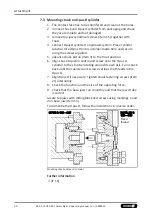
Push the chuck piston (3) into its foremost position.
CAUTION
No stop in front of the piston position
The adaptation between the drawtube and drawbar of the
machine and the chuck piston should be designed that in the stop
is in the clamping cylinder forwards. In the chuck is the stop
backwards. In Fig. 2, is the chuck marked in the maximum
possible front piston position in which the chuck piston not
strikes.
For questions regarding the piston position for self-installation,
contact our technical support service during our business hours.
27
03.00 | ROTA 2B | Assembly and operating manual | en | 0889059

