Maintenance
02.00|1416054_ROTA-M2 + 2 |en-US
49
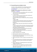
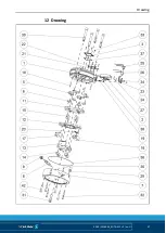
Assembling the lathe chuck
1 Place the chuck body (item 1) with the guideways facing
upwards
2 Slide the base jaws (item 2) into the guideways in the chuck
body (item 1)
CAUTION: The base jaws are numbered; install according to
the numbering on the chuck body!
3 Wrap the sealing element (item 25) snugly around the
projecting base jaws (item 2) and place in the gap between
the chuck body and base jaw.
4 Insert two indicator pins (item 19) and springs (item 38)
respectively into the holes below the guideway in the chuck
body (item 1)
5 Position the O-ring sections (item 26) centrally in the groove
of the cover plates (items 23 and 24) and slide them into the
chuck body (item 1) from below. Make sure that the sealing
element (item 25) is also incorporated into the groove in the
cover plate (items 23 and 24).
CAUTION: Use the cover plates (item 23) on guideways 1 and
4.
6 Fix the cover plates (items 23 and 24) in place with screws
(item 34)
7 Press the projecting O-ring sections (item 26) into the gap
between the chuck body (item 1) and the sealing element
(item 25)
8 Secure the wipers (items 21 and 22) with screws (item 33)
beside the guideways.
9 Press the O-ring (item 37) into the groove in the cover (item 3)
and fasten with screws (item 33) in the middle of the chuck
body (item 1).
10 Slide the base jaws (item 2) into the outer position, turn over
the chuck body (item 1).
11 Insert the bolts (item 18) into the holes in the chuck body
(item 1)
12 Press the indicator pins (item 19) outwards and secure the
position with cylindrical pins (item 48)
13 From the view of the lathe chuck center, insert the wedge bars
(item 5) into the chuck body in the right end position. The
marking must face outwards. Make sure that the serration
7.4


