Assembly
32
02.00|ROTA NCA |en
CAUTION
Use a crane to install the chuck. The chuck can be fastened to
the eye bolt provided (see Fig. "Lathe chuck assembly" - C
The eye bolt must be removed prior to starting up.
The eye bolt is included in the scope of delivery.
Chuck assembly
1 Remove the cylindrical screws (item 27) for the top jaws
together with the T-nuts (item 26).
2 Move the draw tube to the frontmost position.
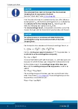
Piston in foremost position R1
= press chuck piston in
foremost position
and measure with depth gauge R2 = R1
–
0.1 mm (max.
–
0.3
mm)
It must be ensured that the piston can be brought into the
foremost (jaw change) position. To do this, ensure that the
dimensions for the attachment are complied with.
3 Push the chuck piston (item 3) to the frontmost position
(chuck open).
4 Lift the lathe chuck flush to the center of the spindle.
5 Screw the rotating center sleeve (item 6) in the chuck onto the
draw tube using the enclosed assembly key as far as this will
go. Chuck without rotatable center sleeve must be bolted
onto the draw tube/pull rod.
6 Insert and slightly tighten the mounting screws (item 10).
7 Check the chuck for concentricity and axial run-out accuracy
(see Fig. "Lathe chuck assembly" - E
) and, if

