Summary of Contents for ROTA NCK plus

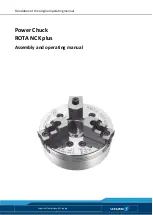
Page 1: ...Translation of the original operating manual Power Chuck ROTA NCK plus Assembly and operating manual Superior Clamping and Gripping ...

Page 2: ...ition 02 00 09 03 2017 en SCHUNK GmbH Co KG All rights reserved Dear customer congratulations on choosing a SCHUNK product By choosing SCHUNK you have opted for the highest precision top quality and best service You are going to increase the process reliability of your production and achieve best machining results to the customer s complete satisfaction SCHUNK products are inspiring Our detailed a...

Page 3: ...orce and speed 22 6 3 1 Calculation of the required clamping force in case of a given rpm 22 6 3 2 Calculation example Required initial clamping force Fsp0 for a given rpm n 24 6 3 3 Calculation of the permissible rpm nzul in case of a given initial clamping force Fsp0 26 6 4 Grades of Accuracy 26 6 5 Permissible imbalance 26 7 Mounting of the Chuck to the Machine Spindle 27 7 1 Inspection of the ...

Page 4: ...sassembly and assembly of the Chuck 37 9 Maintenance 38 9 1 Lubrication 38 9 2 Changing the top jaws 39 9 3 Maintenance intervals 39 10 Disposal 40 11 Assembly drawing 41 12 Spare parts 42 13 Translation of original EC declaration of incorporation 43 ...

Page 5: ...these instructions must also be passed on Illustrations in this manual are provided for basic understanding of the product and may differ from the actual product design We accept no liability for damage resulting from the failure to observe and comply with this operating manual Warnings To make risks clear the following signal words and symbols are used for safety notes DANGER Danger for persons N...

Page 6: ...bout hot surfaces Applicable documents General terms of business Catalog data sheet of the purchased product Calculation of the jaw centrifugal forces Technology chapter in the lathe chuck catalog The documents marked with an asterisk can be downloaded on our homepage www schunk com 1 2 ...

Page 7: ...lso means that the user has read and understood this operating manual in its entirety especially the chapter Basic safety notes The maximum RPM of the chuck and the required clamping force must be determined by the user for the respective clamping task based on the applicable standards and technical specifications of the manufacturer See also Calculations for clamping force and RPM in the chapter ...

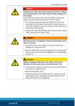
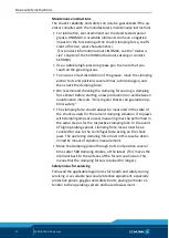
Page 8: ...uck s clamping force until the machine comes to a standstill and the workpiece can be secured e g using a crane or suitable lifting equipment The machines and equipment must fulfill the minimum re quirements of the EC Machinery Directive specifically they must have effective technical measures to protect against po tential mechanical hazards DANGER Possible risk of fatal injury to operating person...

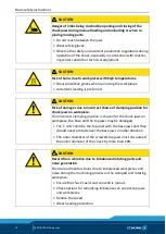
Page 9: ...irnet when working on the machine and the lathe chuck WARNING Risk of injury due to dropping the chuck during transport instal lation or removal Take special care in the danger zone when transporting in stalling or removing the chuck Note the relevant load securing regulations for working safely with cranes ground conveyors lifting gear and load handling equipment CAUTION Danger of slipping and fa...

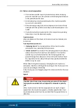
Page 10: ... incorrect choice of clamping position for chuck jaws on workpiece If an incorrect clamping position is chosen for the chuck jaws on workpiece the base and the top jaws may be damaged The T nuts combine the top jaws with the base jaws and they should never protude over the base jaws in radial direction The outer diameter of the screwed top jaws must not exceed the outer diameter of the chuck by mo...

Page 11: ...perating force pressure Stroke control The stroke of the clamping piston must allow a safety zone at the front and rear end position The machine spindle may only be started when the clamping piston has passed through the safety zone Only limit switches that meet the requirements for safety limit switches specified in DIN EN 60204 1 may be used When determining the necessary clamping force to machi...

Page 12: ... production run and between maintenance intervals Only regular checks can guarantee op timal safety The clamping force should always be measured in the state of the chuck as used for the current clamping situation If top jaws with clamping steps are used measuring must be performed in the same step as for the respective clamping task In the event of high operating speeds clamping force losses must...

Page 13: ... use welded jaws If for constructional reasons the chuck jaws in special design are heavier than the top jaws assigned to the clamping device greater centrifugal forces must be accounted for when defining the required clamping force and the recommended speed Screw the jaw mounting screws into the bore holes furthest apart The maximum recommended speed may only be operated in conjunction with maxim...

Page 14: ...instructions the opera tor must ensure that the relevant safety rules are obeyed by the persons asked to operate maintain and repair the chuck Checking the behavior of personnel The operator must at least occasionally check that the personnel are behaving in a safety conscious manner and are aware of the potential hazards Danger signs The operator must ensure that the signs concerning safety and h...

Page 15: ...2 00 ROTA NCK plus en 15 Using personal protective equipment When using this product you must comply with the relevant health and safety at work rules and you must use the required personal safety equipment minimum category 2 2 7 ...

Page 16: ... date under the following con ditions Observe the applicable documents 1 2 Page 6 Observe the ambient conditions and operating conditions Observe the maximum number of clamping cycles 6 Page 19 Observe the specified maintenance and lubrication intervals 9 Page 38 Parts touching the workpiece and wear parts are not included in the warranty 3 ...

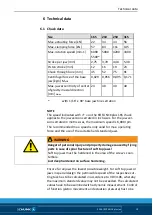
Page 17: ... M18 M20 M22 M24 M27 M30 Admissible torque MA Nm 13 28 50 88 120 160 200 290 400 500 1050 1500 Tightening torques for mounting screws used to attach top jaws onto the chuck screw quality 12 9 Screw size M6 M8 M10 M12 M14 M16 M20 M24 Max admissible torque MA Nm 16 30 50 70 130 150 220 450 Tightening torques for the protection sleeve mounting screws screw quality 8 8 Screw size M4 M5 M6 Tightening t...

Page 18: ...Scope of Delivery 18 02 00 ROTA NCK plus en Scope of Delivery 1 Power chuck 6 Fastening screws 6 T nuts with screws or 3 Jaw Nuts 1 Mounting wrench 1 Eye bolt from size 210 and up 5 ...

Page 19: ...or the jaw ver sion serrated in metric sizes the maximum speed is 6 000 rpm The recommended max speed is only valid for max operating force and the use of the suitable hard standard jaws WARNING Danger of personal injury and property damage caused by flying parts in case of spiral fracture of soft top jaws Soft top jaws must be hardened in the area of the screw s coun terbore Just deep hardened no...

Page 20: ...e operated with the max permissable force and the jaws were located exactly on line with the chuck O D The chuck is in perfect condition and lubricated with SCHUNK LINOMAX special grease Should one or several of the above mentioned parameters be changed the diagrams are no longer valid Chuck set up for clamping force speed diagram F 3 Clamping force per jaw S Center of gravity rs Center of gravity...

Page 21: ...Technical data 02 00 ROTA NCK plus en 21 Clamping force speed diagram ROTA NCKplus 210 52 Clamping force speed diagram ROTA NCKplus 250 75 Clamping force speed diagram ROTA NCKplus 315 91 ...

Page 22: ...ce safety factor mB Mass of clamping jaw set kg sz Machining safety factor Mc Centrifugal force torque kgm Σs Max clamping force of the chuck N Calculation of the required clamping force in case of a given rpm The initial clamping force Fsp0 is the total force impacting radially on the workpiece via the jaws due to actuation of the lathe chuck during shutdown Under the influence of rotation the ja...

Page 23: ...amping force Fspmin Consequently the work piece is released spontaneously Do not exceed the calculated RPM Do not fall below the necessary minimum clamping force Reduction in effective clamping force by the magnitude of the total centrifugal force for gripping from the outside inwards The required effective clamping force for machining Fsp is calculat ed from the product of the machining force Fsp...

Page 24: ...f the initial clamping force The formula for the calculation of the total centrifugal force Fc is For this n is the given speed of rotation in RPM The product mB rs is referred to as the centrifugal force torque Mc In case of toolholders with split chuck jaws i e with base jaws and top jaws for which the base jaws change their radial position only by the stroke amount the centrifugal torque of the...

Page 25: ...nd T nuts are not taken into account First the required effective clamping force Fsp is calculated using the machining force stated Initial clamping force during shutdown Calculation of total centrifugal force For two part chuck jaws the following applies Centrifugal torque of base jaw and top jaw specified in Chuck da ta table For the centrifugal torque of the top jaw the following applies Centri...

Page 26: ...orce for machining job Fspz 3000 N application specific Total centrifugal torque of all jaws Mc 2 668 kgm Safety factor Sz 1 5 according to VDI 3106 Safety factor Ssp 1 5 according to VDI 3106 NOTE Masses of the jaw mounting screws and T nuts are not taken into account Identifying the permissible RPM The calculated RPM nzul 1495 rpm is smaller than the maximum permissible RPM of the chuck nmax 320...

Page 27: ... the Chuck for a vertically suspended machine spindle Inspection of the spindle nose for mounting the chuck flange To achieve high true running of the chuck the machine side must be aligned before mounting the flange Therefore check the receiv ing surface at the spindle for concentricity and runout with a dial indicator maximum run out error of 0 005 mm on the centring mount and a maximum run out ...

Page 28: ... sleeve against turning The spring clamping element is inserted into the drawing piston and presses against the drawing sleeve 3 Cut the same thread into the drawing sleeve as on the draw ing tube 4 Next the drawing sleeve can be inserted back into the chuck 5 Retighten the chuck drawing sleeve using the six screws 1 Screws 4 ROTA NCK 165 the spring clamping element is inte grated directly within ...

Page 29: ...chuck on the machine spindle with a short taper by means of a reduction or extension flange a corresponding chuck flange is attached on the spindle nose 1 Before installing the chuck flange remove any dirt or swarf from the machine spindle and from the centring mount and the contact surface of the flange 2 A chuck flange made by the user himself must be finished ma chining on the machine spindle a...

Page 30: ... the intermediate flange During this it must be ensured that the through holes for attaching the chuck coincide with the threaded holes of the flange figure D 2 Next turn in the fastening screws and tighten them slightly 3 Check the chuck for radial and axial run out figure E and align with slight blows with a hammer on the outer diameter if necessary 4 Next screw the chuck tightly onto the chuck ...

Page 31: ...means of a direct mount When mounting the chuck by means of a direct mount with a through screw connection the flange is first attached to the chuck and subsequently mounted on the spindle Observe the follow ing Observe the following Observe the following 1 Before mounting the chuck flange on the cylindrical recess of the chuck dirt and swarf must be removed from the centring mount and contact sur...

Page 32: ...of the flange figure D 2 Next turn in the fastening screws and tighten them slightly 3 Next check the chuck for radial and axial run out as described in figure E and then tighten the chuck on the chuck flange us ing the fastening screws and a torque wrench During this pay attention to the specified maximum tightening torques 4 Page 17 4 Next check the radial and axial run out as described in figur...

Page 33: ...emove the top jaws complete with the T nuts 12 3 Unscrew the cap head screws 10 and draw out the protec tion sleeve 4 1 Chuck body 15 Draw nut 2 Base jaw 16 Retainer ring 3 Piston A Flange 11 Screws B Mounting wrench 12 T nut NOTE The protection sleeve 4 can be pressed off the chuck body by using the additional threads with the same screws 10 1 Push the tension rod into its foremost position 2 Pus...

Page 34: ...ty and face runout at the control rim 7 1 Page 27 6 Check the function and the size of the operating force 7 Check that the base jaws run smoothly and that the jaw stroke is correct 8 Mount the top jaws firmly on the base jaws with the T nuts 12 and screws according to the markings 1 2 and 3 Dismounting of the spindle is carried out in reverse order NOTE When changing the protection sleeve the chu...

Page 35: ...Mounting of the Chuck to the Machine Spindle 02 00 ROTA NCK plus en 35 Bolt tightening steps ...

Page 36: ... shapes The top jaws are moved or changed in the open clamping position WARNING Clamping further above the chuck surface results in lower clamping force If the workpiece is released in an uncontrolled manner there is a risk of personal injury and damage to the system Refer to the Technical data chapter Replacement or renewal of jaws Clamping jaws for maximum clamping repeat accuracy have to be bor...

Page 37: ... unmounted con dition Mounting of the chuck to the machine spindle 1 Loosen screws 10 and remove the protection sleeve 4 2 Pull the piston 3 out out of the chuck body 1 3 Push the base jaws 2 inwardly out of the base jaw guide NOTE When assembling the base jaws ensure that the number on the base jaw is identical to the numbering on the jaw guide Clean all parts of dirt and grease and check for dam...

Page 38: ...heck the function and the clamping force after a certain time of operation 9 3 Page 39 Clamping force can be measured by using a Grip Force Tester SCHUNK SGT 270 Technical Condition The base jaws must move evenly at the smallest possible operating pressure cylinder This method is only to some extend expressive and cannot replace clamping force measurement If clamping force has dropped too low or i...

Page 39: ...n case of spiral fracture of soft top jaws Soft top jaws must be hardened in the area of the screw s coun terbore Just deep hardened no surface hardening Maintenance intervals Lubrication of the grease areas Lubrication interval Strain every 25 hours normal coolant utilization every 8 hours high coolant utilization after 1200 hours or as needed Total cleaning with disassembly of the chuck dependin...

Page 40: ...the escaping liquids and dispose of them properly in line with the statutory provisions Remove any identifiable plastic or aluminum parts installed in or on the chuck and dispose of them properly in line with the statutory provisions Dispose of the chuck s metal parts as scrap metal Alternatively you can return the chuck to SCHUNK for proper dis posal 10 ...

Page 41: ...Spare parts 02 00 ROTA NCK plus en 41 Assembly drawing 11 ...

Page 42: ...ections springs bearings screws and wiper bars plus parts coming into contact with the workpiece are not covered by the warranty I tem Designation Quantity 1 Chuck body 1 2 Base jaws 3 3 Piston 1 4 Protection sleeve 1 9 Screws 3 10 Screws 3 11 Screws 6 12 T nut 3 13 Grease nipple 3 15 draw nut 1 16 Retainer ring 1 20 Spring clamping element 1 30 Mounting wrench 1 31 Locking bolt 1 32 Eye bolt 1 12...

Page 43: ...07225 0807226 0807230 0807231 0807232 0807235 0807236 0807237 0807240 0807241 0807242 0807243 0807245 0807246 00807246 0807247 0807248 The incomplete machine may not be put into operation until conformity of the machine into which the incomplete machine is to be installed with the provisions of the Machinery Directive 2006 42 EC is confirmed Applied harmonized standards especially DIN EN ISO 12100...

Page 44: ...ion for the partly completed machinery to state offices The relevant technical documentation according to Annex VII Part B belonging to the partly completed machinery have been created Person authorized to compile the technical documentation Philipp Schräder Address see manufacturer s address Mengen August2016 p p Alexander Koch Director for Development Design ...

Reviews: