Mounting
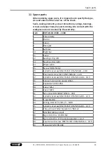
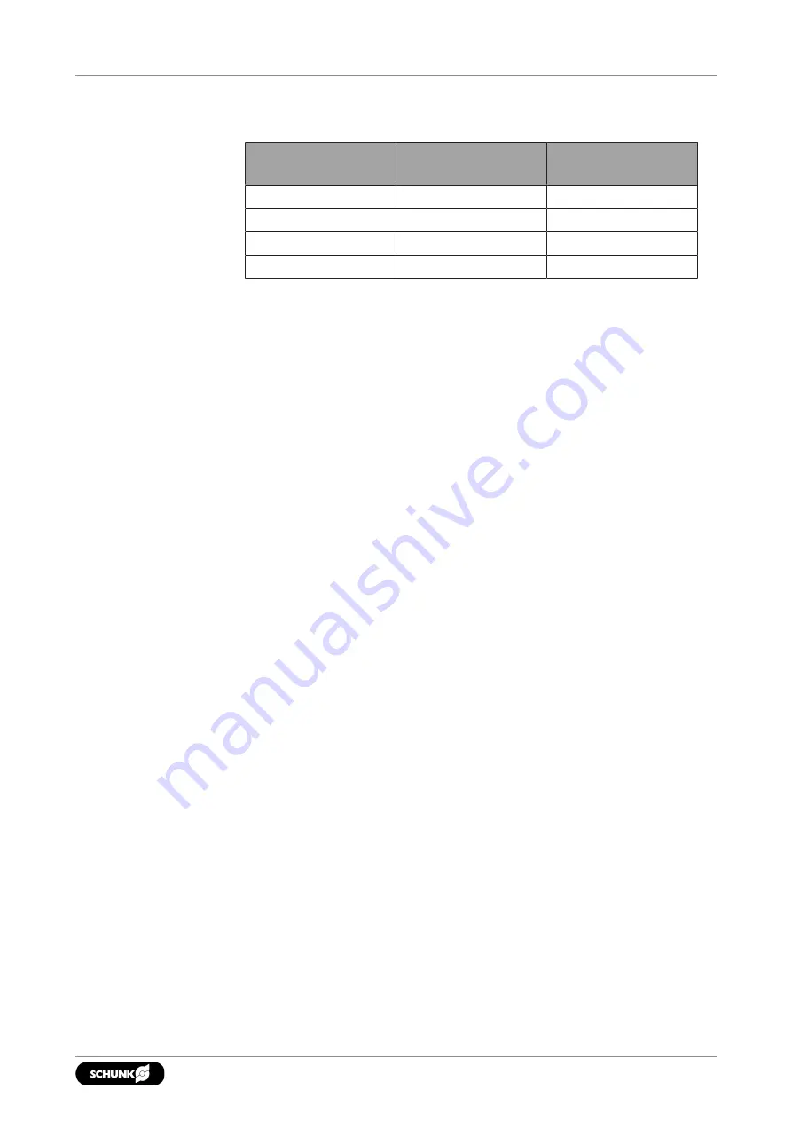
Maximum attainable radial and axial run-out tolerances related
to the chuck
Chuck size [mm]
Max. radial run-out
tolerance [mm]
Max. axial run-out
tolerance [mm]
800
0.06
0.05
1000
0.06
0.05
1200
0.08
0.06
1400
0.08
0.06
• Remove the top jaws with mounting screws and any T-nuts
from the base jaws.
• Move the draw bar to its foremost position by actuating the
clamping cylinder.
• Disassemble the cover.
• Push the chuck piston into the foremost position.
• In principle, it is possible to mount the chuck in two installation
positions (horizontal/vertical), depending on the position of the
machine spindle.
Horizontal mounting of the lathe chuck.
Vertical mounting of the lathe chuck.
7.3 Horizontal attachment
Lift the chuck to the front of the spindle lug using eye bolts flush to
the center of the spindle.
•
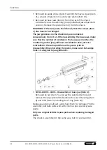
ROTA NCO2 800 – 1400 & ROTA NCO2-JA 800 – 1400:
Turn the chuck on the spindle or machine table until the
mounting holes and spindle flange threads are aligned. Screw
the central mounting screw into the drawbar or the draw tube
adapter with a hexagon socket wrench until the stop.
7.4 Vertical attachment
•
ROTA NCO2 800 – 1400 & ROTA NCO2-JA 800 – 1400:
Turn the chuck on the spindle or machine table until the
mounting holes and spindle flange threads are aligned.
Screw the central mounting screw into the drawbar or the draw
tube adapter with a hexagon socket wrench until the stop.
• Mount the cover.
• Insert and
slightly tighten
the mounting screws.
• Check the chuck for radial and axial run-out and, if necessary,
align it at the outer diameter with gentle taps using a plastic
hammer. (See "Chuck assembly" Fig. - E and the table of the
attainable maximum radial and axial run-out tolerances in the
Assembly chapter)
31
01 | ROTA NCO2, ROTA NCO2-JA | Power Chuck | en | 1506425

