background image


Assembly 


03.00|0889148_ROTA NCX |en 

29 


Assembly 


Installing and connecting 


WARNING 

Risk of injury due to unexpected movements! 

If the power supply is switched on or residual energy remains in 
the system, components can move unexpectedly and cause 
serious injuries. 

  Before starting any work on the product: Switch off the power 

supply and secure against restarting. 

  Ensure that no residual energy remains in the system. 


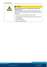
CAUTION 

Danger of injury due to sharp edges and rough or slippery 
surfaces 

  Wear personal protective equipment, particularly protective 

gloves. 


1  Checking the chuck moun

(

 5.3, Page 30)


2  Finish turning the center sleeve blank 

(

 5.2, Page 29)


3  Chuck assembly 

(

 5, Page 29)


4  Performing a functional chec

(

 6.5, Page 34)


Finish turning the center sleeve blank 

Detach the retainer ring (item 10) and remove the center sleeve 
blank (item 11), which is shipped with a only a single bore hole, 
from the piston (item 3). Cut the appropriate draw tube thread 
into the center sleeve blank (item 11). Then reinsert the center 
sleeve (item 11) into the piston (item 3) and screw in the retainer 
ring (item 10). 

Maximum internal thread for center sleeve blanks:


Chuck size 

ROTA NCX 165  ROTA NCX 210  ROTA NCX 260  ROTA NCX 315 

Max. thread 

M60 x 2 

M75 x 2 

M90 x 2 

M115 x 2 


5.1 

5.2 

Summary of Contents for ROTA NCX

Page 1: ...Translation of Original Operating Manual Power chucks ROTA NCX Assembly and Operating Manual Superior Clamping and Gripping ...

Page 2: ... for the purpose of technical improvement Document number 0889148 Version 03 00 05 11 2019 en H D SCHUNK GmbH Co All rights reserved Dear Customer thank you for trusting our products and our family owned company the leading technology supplier of robots and production machines Our team is always available to answer any questions on this product and other solutions Ask us questions and challenge us...

Page 3: ...11 Malfunctions 12 2 12 Disposal 12 2 13 Fundamental dangers 13 2 13 1 Protection during handling and assembly 13 2 13 2 Protection during commissioning and operation 14 2 13 3 Protection against dangerous movements 14 2 13 4 Notes on particular risks 15 3 Technical data 19 3 1 Chuck data 19 3 2 Clamping force speed diagrams 20 3 3 Calculations for clamping force and speed 22 3 3 1 Calculation of ...

Page 4: ...andling the chuck and the base jaws 32 6 3 Base jaw position 33 6 4 Change or supplement of jaws 34 6 5 Functional testing 34 7 Maintenance 36 7 1 Lubrication 36 7 2 Maintenance intervals 37 7 3 Technical condition 37 7 4 Disassembling and assembling the chuck 38 8 Chuck mounts and Spare parts 40 8 1 Chuck mounts 40 8 2 Spare parts 40 9 Drawing 42 10 Translation of the original declaration of inco...

Page 5: ...trations in this manual are provided for basic understanding and may differ from the actual product design In addition to these instructions the documents listed under 1 1 2 Page 6 are applicable Presentation of Warning Labels To make risks clear the following signal words and symbols are used for safety notes DANGER Danger for persons Non observance will inevitably cause irreversible injury or de...

Page 6: ... 106 Warranty The warranty period is 24 months after delivery date from factory or 500 000 cycles if it is used as intended under the following conditions Observe the applicable documents 1 1 2 Page 6 Observe the ambient conditions and operating conditions 2 6 Page 9 Observe the specified maintenance and lubrication intervals 7 Page 36 Parts touching the workpiece and wear parts are not included i...

Page 7: ...pective clamping task based on the applicable standards and technical specifications of the manufacturer See also Calculations for clamping force and RPM in the chapter Technical data 3 Page 19 Not intended use A not intended use of the product is for example It is used as a press a punch a toolholder a load handling device or as lifting equipment the product is used for unintended machines or wor...

Page 8: ...uck jaws if no residual energy can be released Do not use welded jaws The jaws should be designed as light and as low as possible The clamping point must be as close as possible to the chuck face clamping points at a greater distance lead to greater surface pressure in the jaw guidance and can significantly reduce the clamping force If for constructional reasons the special chuck jaws are heavier ...

Page 9: ...ication parameters 3 Page 19 Make sure that the product is a sufficient size for the application Only use high quality cooling emulsions with anti corrosive additives during processing Clamping force tester Depending on the operating conditions the function and clamping force must be checked after a certain period of operation 7 2 Page 37 Only use a calibrated clamping force tester for measuring d...

Page 10: ...oduct Due to their technical training knowledge and experience trained electricians are able to work on electrical systems recognize and avoid possible dangers and know the relevant standards and regulations Due to its technical training knowledge and experience qualified personnel is able to perform the delegated tasks recognize and avoid possible dangers and knows the relevant standards and regu...

Page 11: ...ng hazardous substances Wear close fitting protective clothing and also wear long hair in a hairnet when dealing with moving components Notes on safe operation Incorrect handling of the personnel Incorrect handling and assembly may impair the product s safety and cause serious injuries and considerable material damage Avoid any manner of working that may interfere with the function and operational...

Page 12: ...tions Immediately remove the product from operation and report the malfunction to the responsible departments persons Order appropriately trained personnel to rectify the malfunction Do not recommission the product until the malfunction has been rectified Test the product after a malfunction to establish whether it still functions properly and no increased risks have arisen Disposal Handling of di...

Page 13: ...ion Protection during handling and assembly Incorrect handling and assembly Incorrect handling and assembly may impair the product s safety and cause serious injuries and considerable material damage Have all work carried out by appropriately qualified personnel For all work secure the product against accidental operation Observe the relevant accident prevention rules Use suitable assembly and tra...

Page 14: ...stalled monitors become effective it must be assumed that the drive movement is faulty with its action being dependent on the control unit and the current operating condition of the drive Perform maintenance work modifications and attachments outside the danger zone defined by the movement range To avoid accidents and or material damage human access to the movement range of the machine must be res...

Page 15: ...clamping force may fail immediately and the workpiece may be released in an uncontrolled manner This poses a risk of death or injury to the operating personnel and can result in serious damage to the automated system The machine manufacturer and the operator of the machine must carry out and document a hazard assessment and risk analysis to ensure that suitable measures are taken to maintain the l...

Page 16: ...ght on the lathe chuck and being dragged into the machine Loose clothing or long hair may become caught on projecting parts of the lathe chuck and be drawn into the machine The machines and equipment must fulfill the minimum requirements of the EC Machinery Directive specifically they must have effective technical measures to protect against potential mechanical hazards Always wear tight fitting c...

Page 17: ...ing centers and other technical equipment CAUTION Risk of burns due to workpieces with high temperatures Wear protective gloves when removing the workpieces Automatic loading is preferred CAUTION Risk of damage due to incorrect choice of clamping position for chuck jaws on workpiece If an incorrect clamping position is chosen for the chuck jaws on workpiece the base and top jaws may break Make sur...

Page 18: ...d noise generation Physical and mental strains due to imbalanced workpieces and noise during the machining process on the clamped and rotating workpiece Ensure the chuck s axial and concentric runout Check options for remedying imbalances on special top jaws and workpieces Reduce the speed Wear hearing protection ...

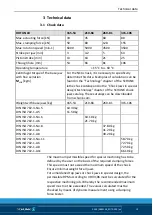
Page 19: ...d from schunk com Weight with base jaws kg 165 53 210 66 260 81 315 106 DIN ISO 702 4 No 5 DIN ISO 702 1 A5 10 30 kg 11 50 kg DIN ISO 702 4 No 6 DIN ISO 702 1 A6 18 10 kg 21 70 kg DIN ISO 702 4 No 8 DIN ISO 702 1 A6 DIN ISO 702 1 A8 37 80 kg 41 20 kg 39 20 kg DIN ISO 702 4 No 11 DIN ISO 702 1 A6 DIN ISO 702 1 A8 DIN ISO 702 1 A11 58 70 kg 72 70 kg 72 50 kg 66 10 kg The maximum permissible speed fo...

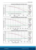
Page 20: ...applied and the jaws were set flush with the outer diameter of the chuck The chuck is in perfect condition and lubricated with SCHUNK LINOMAX plus special grease If one or more of these prerequisites is modified the graphs will no longer be valid Chuck setup for clamping force RPM diagram F 3 Clamping force per jaw Fmax Max actuating force rs Center of gravity radius S Center of gravity Clamping f...

Page 21: ...Technical data 03 00 0889148_ROTA NCX en 21 Clamping force RPM graph for ROTA NCX 210 66 Clamping force RPM graph for ROTA NCX 260 81 Clamping force RPM graph for ROTA NCX 315 106 ...

Page 22: ...set kg sz Safety factor for machining Mc Centrifugal force torque Nm Σs Max clamping force of chuck N kgm 9 81 Nm Calculation of the required clamping force in case of a given rpm The initial clamping force Fsp0 is the total force impacting radially on the workpiece via the jaws due to actuation of the lathe chuck during shutdown Under the influence of rotation the jaw mass generates an additional...

Page 23: ...workpiece is released spontaneously Do not exceed the calculated RPM Do not fall below the necessary minimum clamping force Reduction in effective clamping force by the magnitude of the total centrifugal force for gripping from the outside inwards The required effective clamping force for machining Fsp is calculated from the product of the machining force FspZ and the safety factor Sz This factor ...

Page 24: ... and the rpm CAUTION For safety reasons in accordance with DIN EN 1550 the centrifugal force may be a maximum of 67 of the initial clamping force The formula for the calculation of the total centrifugal force Fc is For this n is the given speed of rotation in RPM The product mB rs is referred to as the centrifugal force torque Mc In case of toolholders with split chuck jaws i e with base jaws and ...

Page 25: ...plication specific Center of gravity radius of top jaw rsAB 0 107 m application specific Safety factor Sz 1 5 according to VDI 3106 Safety factor Ssp 1 5 according to VDI 3106 Note Masses of the jaw mounting screws and T nuts are not taken into account First the required effective clamping force Fsp is calculated using the machining force stated Initial clamping force during shutdown Calculation o...

Page 26: ...initial clamping force during shutdown CAUTION The calculated permissible RPM may not exceed the maximum RPM inscribed on the chuck for safety reasons Example of calculation Permissible RPM for a given effective clamping force The following data is known from previous calculations Initial clamping force during shutdown Fsp0 17723 N Machining force for machining job Fspz 3000 N application specific...

Page 27: ...ible imbalance DIN ISO 21940 11 The ROTA NCX in ungreased state without chuck jaws corresponds to the balancing quality class 6 3 according to DIN ISO 21940 11 Residual imbalance risks may arise due to insufficient rotation compensation being achieved see DIN EN 1550 6 2 e This applies particularly to high speeds asymmetrical workpieces or the use of various chuck jaws as well as uneven applicatio...

Page 28: ...r suitable technical equipment screw quality 10 9 Screw size M6 M8 M10 M12 M14 M16 M18 M20 M22 M24 M27 M30 Admissible torque MA Nm 13 28 50 88 120 160 200 290 400 500 1050 1500 Tightening torques for the fastening screws of the quick change jaw system bolt quality 12 9 Screw size M8 M10 M12 M16 M20 M24 Tightening torque Nm 25 60 80 100 180 230 4 ...

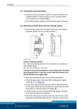
Page 29: ... particularly protective gloves 1 Checking the chuck mount 5 3 Page 30 2 Finish turning the center sleeve blank 5 2 Page 29 3 Chuck assembly 5 Page 29 4 Performing a functional check 6 5 Page 34 Finish turning the center sleeve blank Detach the retainer ring item 10 and remove the center sleeve blank item 11 which is shipped with a only a single bore hole from the piston item 3 Cut the appropriate...

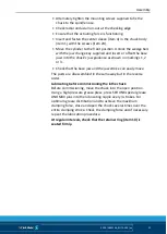
Page 30: ...easure with a depth gauge R2 R1 0 1 mm max 0 3 mm You have to ensure that the piston can be moved to the foremost jaw change position To do this ensure that the dimensions for the attachment are complied with Move the chuck piston item 3 to its foremost position Offset the base jaws to the outermost marking see chapter Drawings 9 Page 42 Remove the screws item 24 and use the threaded extraction ho...

Page 31: ...s shown on markings 1 2 or 3 Check that the base jaw and the jaw stroke can easily move The parts are disassembled in the same way but in the reverse order Lubricating before commissioning the lathe chuck Before commissioning move the chuck into the open position Using a high pressure grease press press SCHUNK special grease LINOMAX plus into the lubricating nipple every 3 strokes For optimum grea...

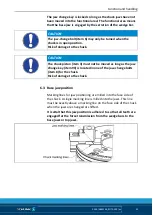
Page 32: ... is determined by the clamping cylinder The base jaws with screwed on top jaws are moved or changed in the open clamping position For safety reasons the serration for the base jaws is still half engaged in this chuck piston position The base jaws are unlocked manually CAUTION There is a risk of crushing during manual loading due to the large jaw stroke We recommend automatic loading If manual load...

Page 33: ... piston item 3 must not be moved as long as the jaw change key item 90 is located in one of the jaw change bolts item 8 for the chuck Risk of damage to the chuck Base jaw position Marking lines for jaw positioning are milled into the face side of the chuck A single marking line is milled into the jaws This line must be exactly above a marking line on the face side of the chuck when the jaws are ch...

Page 34: ...th hammer blows Functional testing Functional test After installation of the chuck its function must be checked prior to start up Two important points are Clamping Force The clamping force of the chuck must be achieved at max operating force pressure Stroke control The stroke of the clamping piston must allow a safety zone at the front and rear end position The machine spindle may only be started ...

Page 35: ...of fatal injury to operating personnel if the top speed is exceeded resulting in workpiece loss and parts flying off A reliable speed limiter must be installed in the machine tool or technical equipment and proof must be provided that the speed limiter is effective ...

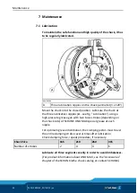
Page 36: ...ing a high pressure grease gun with two to six strokes depending on the chuck side of SCHUNK LINO MAX special grease at each nipple For optimum grease distribution the clamping piston must travel the entire clamping stroke several times after lubrication Check clamping force repeat procedure if necessary Chuck Size 165 210 260 315 Number of strokes 2 4 4 6 Lubricate all three segments evenly in or...

Page 37: ...sure clamping cylinder the base jaws should move evenly This method only provides a limited indication and does not replace the measurement of the clamping force If the clamping force has dropped too far or if the base jaws and clamping piston no longer move properly the chuck has to be disassembled cleaned and relubricated Functional test when changing jaws If a jaw is removed from the jaw guidan...

Page 38: ...uck body item 1 using the wedge bars item 5 paying attention to the balls item 22 in the wedge bars item 5 Remove the bolt item 9 from the wedge bar item 4 and use a punch to drive out the cylindrical pin item 21 toward the center of the chuck Remove the spring item 28 and the monitoring pin item 8 from the wedge bar item 5 Unscrew the ring item 10 from the piston item 3 and remove the center slee...

Page 39: ...e piece item 33 on the wrench and screw it in backwards Determine the depth of engagement together with chuck body pos 1 and base jaws pos 2 Only original SCHUNK spare parts may be used The lathe chuck is assembled in the same way but in the reverse order Before installation lubricate parts well with LINO MAX plus special grease paste CAUTION Allergic reactions due to grease in contact with skin W...

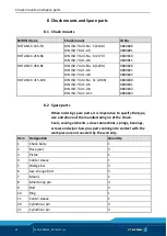
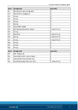
Page 40: ...300 DIN ISO 702 1 A6 DIN ISO 702 1 A8 DIN ISO 702 1 A11 0800830 0800831 0800832 0800833 Spare parts When ordering spare parts it is imperative to specify the type size and above all the manufacturing no of the chuck Seals sealing elements screw connections springs bearings screws and wiper bars plus parts coming into contact with the workpiece are not covered by the warranty Item Designation Quant...

Page 41: ...Screw 3 27 Spring 3 29 Lubrication nipple 3 33 Spring loaded pressure pieces 3 size 315 6 34 O ring 1 35 Steel ball 3 size 315 0 36 Spring 3 size 315 0 37 O ring 3 size 315 0 38 O ring 1 39 O ring 1 40 O ring 3 Item Designation Quantity 49 Jaw change key 1 50 Assembly tool for center sleeve 1 51 Locking bolt for assembly tool 1 52 Eye bolt starting from size 210 1 size 165 0 ...

Page 42: ...Drawing 42 03 00 0889148_ROTA NCX en Drawing 9 ...

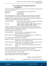
Page 43: ...ted machine is to be installed with the provisions of the Machinery Directive 2006 42 EC is confirmed Applied harmonized standards especially EN ISO 12100 2010 Safety of machinery General principles for design Risk assessment and risk reduction EN 1550 1997 A1 2008 Machine tools safety Safety requirements for the design and construction of work holding chucks Other related technical standards and ...

Page 44: ...ing X 1 2 Control Systems 1 2 1 Safety and reliability of control systems X 1 2 2 Control devices X 1 2 3 Starting X 1 2 4 Stopping X 1 2 4 1 Normal stop X 1 2 4 2 Operational stop X 1 2 4 3 Emergency stop X 1 2 4 4 Assembly of machinery X 1 2 5 Selection of control or operating modes X 1 2 6 Failure of the power supply X 1 3 Protection against mechanical hazards 1 3 1 Risk of loss of stability X ...

Page 45: ...1 2 Warning devices X 1 7 2 Warning of residual risks X 1 7 3 Marking of machinery X 1 7 4 Instructions X 1 7 4 1 General principles for the drafting of instructions X 1 7 4 2 Contents of the instructions X 1 7 4 3 Sales literature X The classification from Annex 1 is to be supplemented from here forward 2 Supplementary essential health and safety requirements for certain categories of machinery X...

Reviews: