Assembly
30
03.00|0889148_ROTA NCX |en
Checking the chuck mounting
•
Check the machine spindle head or the ready-machined inter-
mediate flange for radial and axial run-out. The permissible
limit is 0.005 mm as per DIN 6386-1.
•
The contact surface must be chamfered and clean at the bores.
Mounting the lathe chuck onto the machine spindle
•
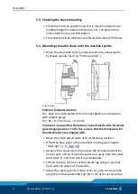
Move the draw tube to its foremost position by actuating the
hydraulic cylinder (see Fig. "Piston position").
Piston position
Piston in foremost position
R1 = Push the chuck piston to its foremost position and measure
with a depth gauge
R2 = R1
–
0.1 mm (max.
–
0.3 mm)
You have to ensure that the piston can be moved to the foremost
(jaw change) position. To do this, ensure that the dimensions for
the attachment are complied with.
•
Move the chuck piston (item 3) to its foremost position.
•
Offset the base jaws to the outermost marking (see chapter
"Drawings"
•
Remove the screws (item 24) and use the threaded extraction
hole to push off the center sleeve (item 4) away from the chuck
body (item 1), and then pull it out completely.
•
Lift the chuck to the front of the spindle lug using an eye bolt
flush with the center of the spindle.
•
Screw the rotating center sleeve (item 11) onto the draw tube
using the enclosed assembly tool (item 19) as far as this will go.
5.3
5.4


