Assembly
30
06.00 | ROTA THW3 | Power Chuck | en | 1440828
5.4.1 Chuck assembly (with cylindrical recess)
NOTE
If the mount of the machine spindle and the lathe chuck are
identical, chuck assembly takes place without assembly
preparation.
If the mount of the machine spindle differs from that of the lathe
chuck, a connecting flange must be affixed before the chuck is
assembled.
).
NOTICE
Use a crane to install the lathe chuck. The chuck can be fastened
to the eye bolt provided (see Fig. "Lathe chuck assembly" -
C
The eye bolt must be removed prior to commissioning.
The eye bolt is included in the scope of delivery (from size 225).
Chuck assembly
• Move the draw tube to its foremost position by actuating the
clamping cylinder
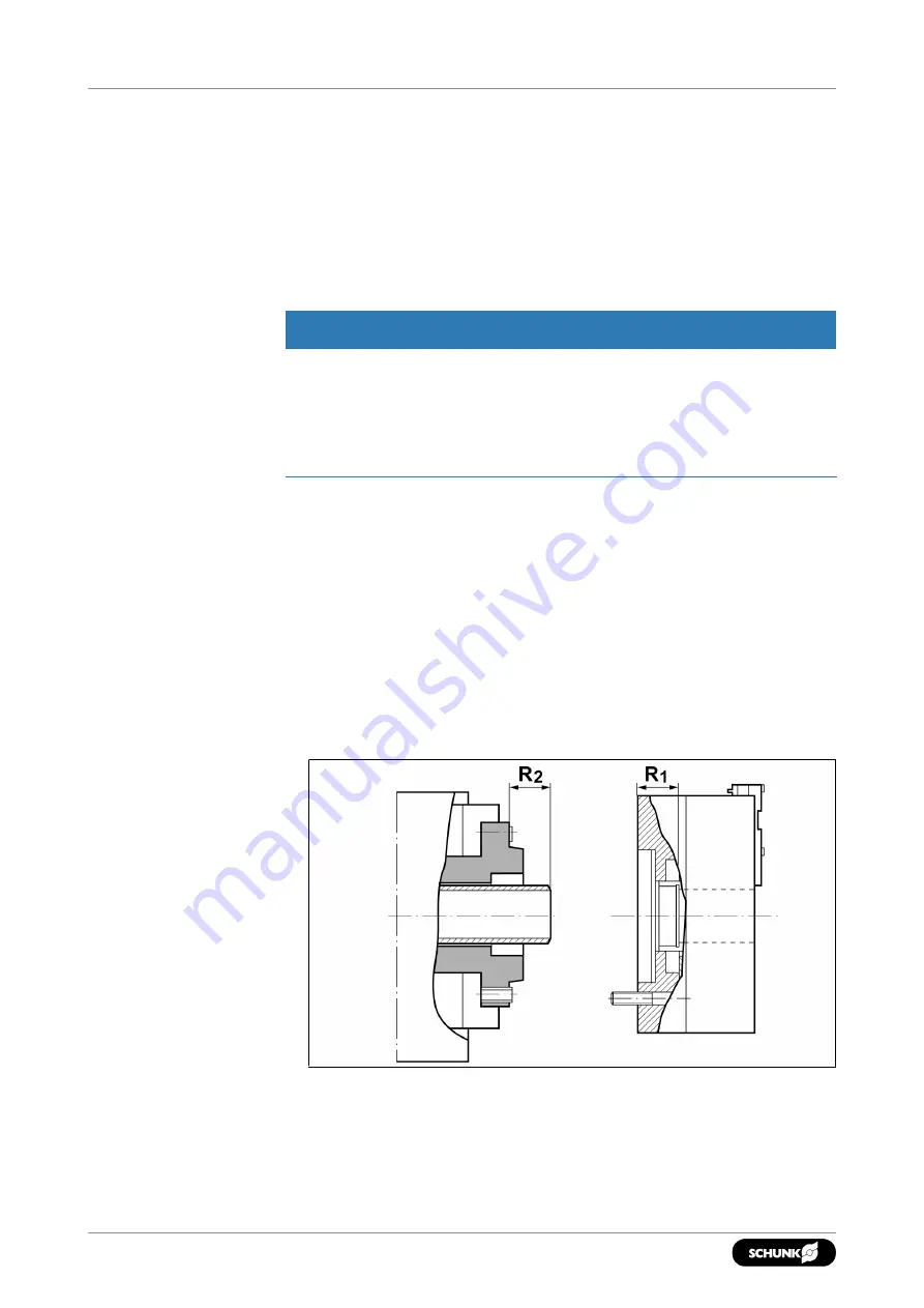
Piston in foremost position
R1 = Push the chuck piston to its foremost position and measure
with a depth gauge.
R2 = R1 + 0.3 mm
(max. + 0.5 mm)
Ensure that the piston can be moved to its foremost position
(jaw change). To do this, ensure that the dimensions for the
attachment are complied with.
Lathe chuck
Hydraulic Cylinder
• Push the chuck piston to its foremost position.
Summary of Contents for ROTA THW3
Page 1: ...Translation of Original Operating Manual Power Chuck ROTA THW3 Assembly and Operating Manual ...
Page 46: ...Drawing 46 06 00 ROTA THW3 Power Chuck en 1440828 9 Drawing Full chuck Accessories ...
Page 47: ...Drawing Thrust jaw 47 06 00 ROTA THW3 Power Chuck en 1440828 ...
Page 48: ...Drawing 48 06 00 ROTA THW3 Power Chuck en 1440828 Mount ...
Page 49: ...Drawing Thread lock with Klemm tight 49 06 00 ROTA THW3 Power Chuck en 1440828 ...
Page 54: ......
Page 55: ......


