


Assembly
30
01.00|ROTA THW vario |en-US
Assembly
Mounting the lathe chuck onto the machine spindle
Checking the chuck mounting
• Check the machine spindle nose and ready-machined
intermediate flange for cencentricity and axial run-out. The
permissible limit is 0.005 mm in accordance with DIN 6386 and
ISO 3089.
• The contact surface must be chamfered and clean at the bore
holes.
Attaching the THW vario chuck
• Remove the chuck from its packaging and check for
damage/completeness.
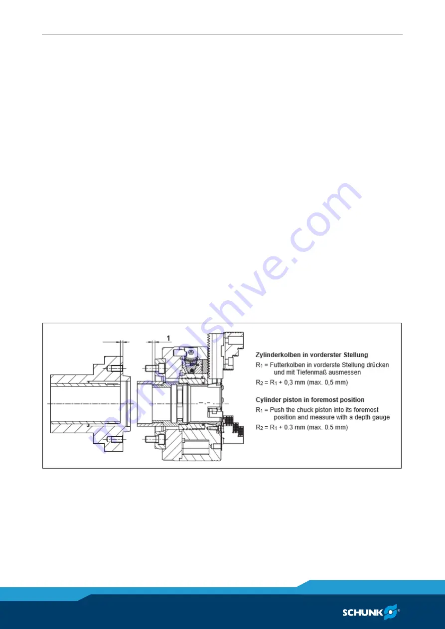
• Move the draw tube to its foremost position by actuating the
clamping cylinder (see Image 6.1).
NOTE
It is important to make sure that the piston can be moved to the
foremost (jaw change) position. To do this, ensure compliance
with the dimensions for the attachment (Image 6.1).
Image 6.1
8
8.1
Summary of Contents for ROTA THWvario
Page 60: ...Assembly drawing 60 01 00 ROTA THW vario en US Assembly drawing ROTA THW vario 215 62 13 13 1 ...
Page 61: ...Assembly drawing 01 00 ROTA THW vario en US 61 ...
Page 62: ...Assembly drawing 62 01 00 ROTA THW vario en US Segmented mandrel ROTA THW vario D 13 1 1 ...
Page 63: ...Assembly drawing 01 00 ROTA THW vario en US 63 Collet chuck ROTA THW vario F 13 1 2 ...


