


Assembly
34
01.00|ROTA THW vario |en-US
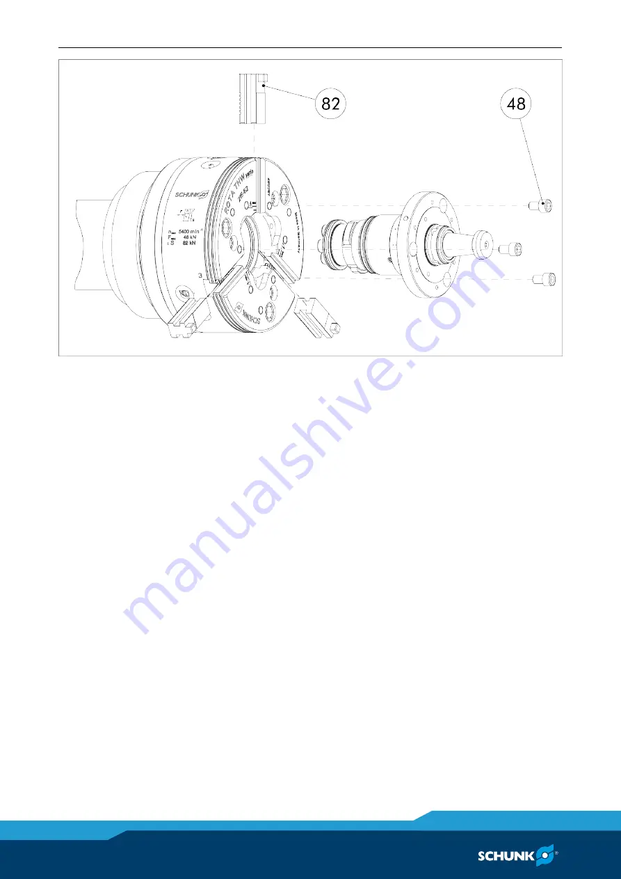
1 Remove chuck jaw (item 2) from the chuck and insert
protective jaws (item 82) up to the max. position (marking on
chuck face).
NOTE
The mechanical system of the chuck is opened when the center
sleeve or the vario component are changed. No chips may
penetrate into the mechanical system of the chuck.
2 Remove center sleeve (item 4). To do this, remove the screws
(item 43) and screw them into the adjacent threads to press
the center sleeve off.
3 Clean the taper, the flat surfaces and the bayonet before
assembly.
4 Insert the vario component into the lathe chuck so that the
marking on the circumference of the vario is aligned with the
base jaw guide. The bayonets can be slid into each other in
this position.
5 Tighten vario with 3 screws (item 48) on the chuck face
(screws: DIN EN ISO 4762 - M10-10.9 tightened to a torque of
53 Nm). The vario component is fixed free from play in the
lathe chuck.
6 Change the clamping pressure on the hydraulics to the
actuating force of the vario.
Summary of Contents for ROTA THWvario
Page 60: ...Assembly drawing 60 01 00 ROTA THW vario en US Assembly drawing ROTA THW vario 215 62 13 13 1 ...
Page 61: ...Assembly drawing 01 00 ROTA THW vario en US 61 ...
Page 62: ...Assembly drawing 62 01 00 ROTA THW vario en US Segmented mandrel ROTA THW vario D 13 1 1 ...
Page 63: ...Assembly drawing 01 00 ROTA THW vario en US 63 Collet chuck ROTA THW vario F 13 1 2 ...


