Assembly
01.00|ROTA THW vario |en-US
41
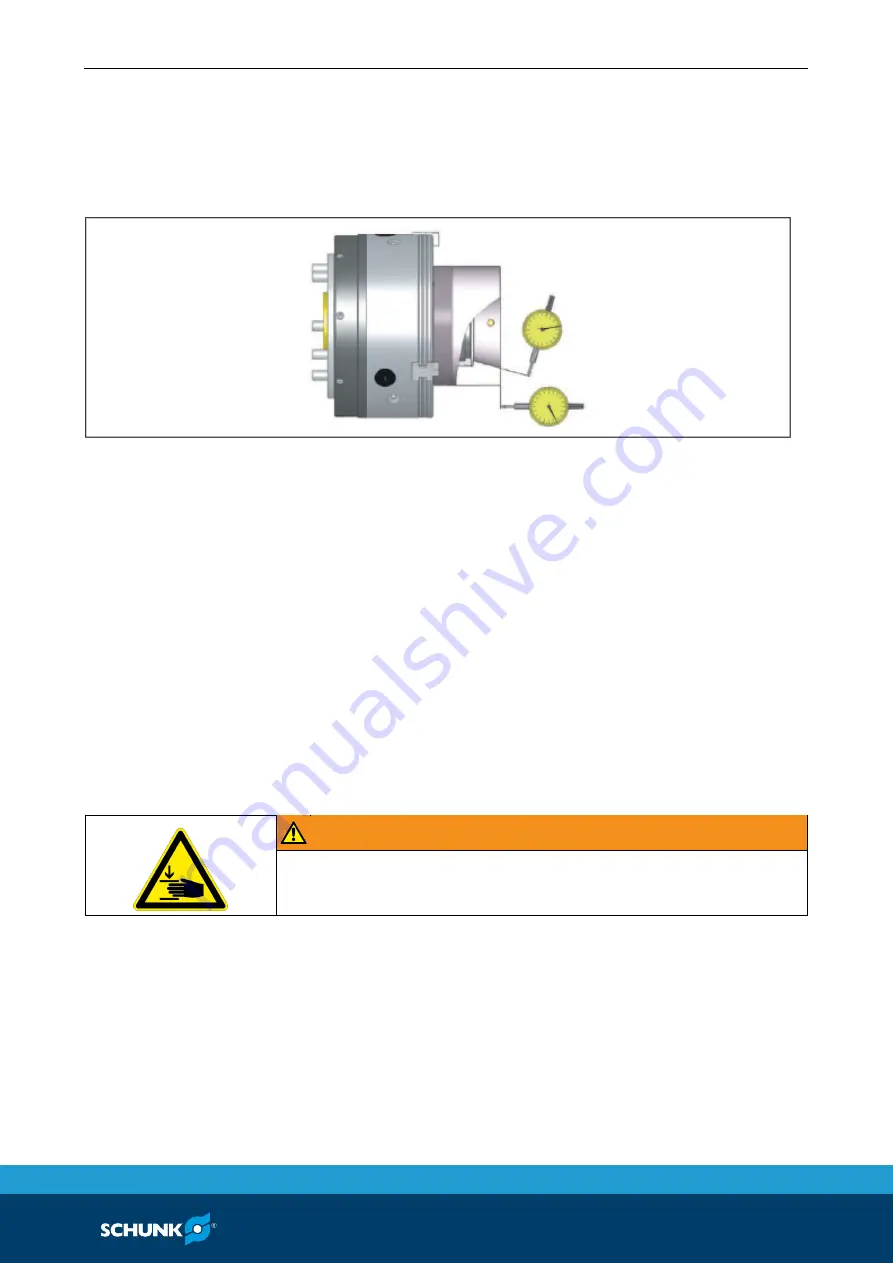
Furthermore, concentricity can only be achieved by improved
alignment of the power chuck.
If necessary, the mounting position of the vario F must be marked
to a specific position to achieve optimum repeat clamping
accuracy.
Replacing vario F clamping head
The clamping head can only be changed in the release position of
the power chuck. Before replacing a clamping head (item 1), clean
the clamping taper in the chuck body (item 2). Place the changing
device on the clamping head. Insert the axis-parallel pins of the
changing device completely into the frontal changing bores of the
clamping head. By actuating the changing device, the clamping
head (item 1) is compressed in the coupling area. Insert the
clamping head into the chuck body with the fixing bolts (item 6)
engaging in the milled fixing grooves (item 17) in the segment
centers (never in the vulcanized slots).
Use slight pressure to loosen and pull out the changing device in
the spindle direction.
WARNING
When operating the changing device, do not reach into the
moving parts due to the risk of crushing.
Remove the SPANNTOP clamping head
The clamping head can only be removed in the release position of
the chuck. Place the changing device on the clamping head. Insert
the axis-parallel pins of the changing device completely into the
front changing bores of the clamping head. By actuating the
changing device, the clamping head (item 1) is compressed in the
coupling area. Remove the changing device with the clamping
head from the lathe chuck, loosen the changing device and
remove the clamping head.
8.3.2
Summary of Contents for ROTA THWvario
Page 60: ...Assembly drawing 60 01 00 ROTA THW vario en US Assembly drawing ROTA THW vario 215 62 13 13 1 ...
Page 61: ...Assembly drawing 01 00 ROTA THW vario en US 61 ...
Page 62: ...Assembly drawing 62 01 00 ROTA THW vario en US Segmented mandrel ROTA THW vario D 13 1 1 ...
Page 63: ...Assembly drawing 01 00 ROTA THW vario en US 63 Collet chuck ROTA THW vario F 13 1 2 ...


