Commissioning and maintenance
02.00|ROTA TP |en
45
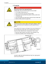
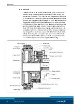
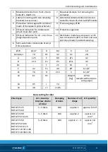
1 Mounted directly from front: 2 bore
holes Ø L, depth C4
7 Required distance for removing the
container
2 Lateral mounting with two retaining
brackets (accessories)
8 Automatic condensate drain can be con-
nected by means of a hose with Ø 6 inside
3 Protective metal cage with container
made of transparent polycarbonate
9 Pressure gauge, Ø 40
4 Fill level indication for condensate
(small inspection port)
10 Protective cage lock
5 Fill level indication for oil – min./max.
(large inspection port)
11 Distributor module as accessory: with
two connections (Ø T) at front and rear
and one already mounted seal plug
6 Semi-automatic condensate drain, G
1/8 connection
Ø W
G 1/4”
D
84
K
10
Container
7 cl
D1
42
K1
28
A
125
E
89
Ø L
4.1
B
213
E1
65
Ø L1
4.5
B1
-
F
21
M
3
C
42
F1
40
Ø T
G 1/8”
C1
76
H
215
V
G 1/8”
C2
61
H1
-
Weight
[kg]
0.760
(weight without pres-
sure gauge)
C3
95
J
74
C4
38
J1
110.5
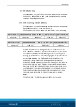
Basic setting for oiler
Chuck type
Air consump-
tion/jaw stroke
at 6 bar
Clamping
strokes
Number of oil
drops
Oil quantity
ROTA TP 125
ROTA TP 160
1 – 3 liters
100
approx. 1
approx. 6 mm
3
ROTA TP 200
ROTA TP 315-105
3 – 5 liters
100
approx. 2
approx. 12
mm
3
ROTA TP 250
ROTA TP 315-90
ROTA TP 315-115
ROTA TP-LH 315-105
ROTA TP-LH 350-115
5 – 8 liters
100
approx. 2 - 3
approx. 18
mm
3


