background image


Basic safety notes  


02.00|ROTA TP |en 


Basic safety notes  


Intended use 

This product is intended for clamping workpieces on machine tools 

and other suitable technical devices. 
  •  The product may only be used within the scope of its technical 

data, 

(

 3, Page 17)

. 

  •  The product is intended for industrial and industry-oriented use. 
  •  Appropriate use of the product includes compliance with all in-

structions in this manual. 

  •  The maximum RPM of the chuck and the required clamping 

force must be determined by the user for the respective clamp-

ing task based on the applicable standards and technical speci-

fications of the manufacturer. 

(See also “Calculations for clamping force and RPM” in the 

chapter “Technical data”). 

(

 3, Page 17)


Not intended use 

A not intended use of the product is for example: 
  •  It is used as a press, a punch, a toolholder, a load-handling device or 

as lifting equipment. 

  •  the product is used for unintended machines or workpieces. 
  •  the technical data is exceeded when using the product. 

(

 3, Page 17)


  •  if workpieces are not clamped properly, paying particular at-

tention to the clamping forces specified by the manufacturer. 

  •  if it is used in working environments that are not permissible. 
  •  if the product is operated without a protective cover. 


Constructional changes 

Implementation of structural changes


By conversions, changes, and reworking, e.g. additional threads, 

holes, or safety devices can impair the functioning or safety of the 

product or damage it. 
  •  Structural changes should only be made with the written ap-

proval of SCHUNK. 

2.1 

2.2 

2.3 

Summary of Contents for ROTA TP

Page 1: ...Translation of the original manual Pneumatic Chuck ROTA TP ROTA TP LH Assembly and operating manual Superior Clamping and Gripping ...

Page 2: ...he purpose of technical improvement Document number 0889118 en Version 02 00 24 10 2017 en H D SCHUNK GmbH Co All rights reserved Dear Customer thank you for trusting our products and our family owned company the leading technol ogy supplier of robots and production machines Our team is always available to answer any questions on this product and other solutions Ask us questions and challenge us W...

Page 3: ... 2 11 Malfunctions 11 2 12 Disposal 11 2 13 Fundamental dangers 12 2 13 1 Protection during handling and assembly 12 2 13 2 Protection during commissioning and operation 12 2 13 3 Protection against dangerous movements 13 2 13 4 Notes on particular risks 13 3 Technical data 17 3 1 Chuck data 17 3 2 Clamping force speed diagrams 18 3 3 Calculations for clamping force and speed 21 3 3 1 Calculation ...

Page 4: ...ring 35 6 3 1 Distributor ring normal fastening 35 6 3 2 Stationary mounting of the distributor ring 37 6 3 3 Mounting with bracket 39 6 3 4 Mounting with 2 part clamping ring D R M B 40 7 Commissioning and maintenance 43 7 1 Initial operation 43 7 2 Maintenance 44 7 3 Maintenance intervals 47 7 4 Hardened Reversible Jaws and Soft Top Jaws 47 7 5 Disassembly 48 7 6 Assembly 49 8 Spare parts 51 9 A...

Page 5: ...ations in this manual are provided for basic understanding and may differ from the actual product design In addition to these instructions the documents listed under 1 1 2 Page 6 are applicable Presentation of Warning Labels To make risks clear the following signal words and symbols are used for safety notes DANGER Danger for persons Non observance will inevitably cause irreversible injury or deat...

Page 6: ...ivery date from factory or 500 000 cycles if it is used as intended under the following conditions Observe the applicable documents 1 1 2 Page 6 Observe the ambient conditions and operating conditions 2 6 Page 9 Observe the specified maintenance and lubrication intervals 7 Page 43 Parts touching the workpiece and wear parts are not included in the warranty A cycle consists of a complete clamping p...

Page 7: ...d RPM in the chapter Technical data 3 Page 17 Not intended use A not intended use of the product is for example It is used as a press a punch a toolholder a load handling device or as lifting equipment the product is used for unintended machines or workpieces the technical data is exceeded when using the product 3 Page 17 if workpieces are not clamped properly paying particular at tention to the c...

Page 8: ... to greater surface pressure in the jaw guidance and can significantly reduce the clamping force If for constructional reasons the special chuck jaws are heavier than the top jaws assigned to the lathe chuck greater centrifu gal forces must be accounted for when defining the required clamping force and the recommended speed The maximum recommended speed may only be operated in conjunction with max...

Page 9: ...ore working with the product the personnel must have read and understood the complete assembly and operating manual Observe the national safety regulations and rules and general safety instructions The following personal qualifications are necessary for the various activities related to the product Due to their technical training knowledge and experience trained electricians are able to work on el...

Page 10: ...z ardous substances Wear close fitting protective clothing and also wear long hair in a hairnet when dealing with moving components Notes on safe operation Incorrect handling of the personnel Incorrect handling and assembly may impair the product s safety and cause serious injuries and considerable material damage Avoid any manner of working that may interfere with the func tion and operational sa...

Page 11: ... Immediately remove the product from operation and report the malfunction to the responsible departments persons Order appropriately trained personnel to rectify the malfunc tion Do not recommission the product until the malfunction has been rectified Test the product after a malfunction to establish whether it still functions properly and no increased risks have arisen Disposal Handling of dispos...

Page 12: ... serious injuries and considerable material damage Have all work carried out by appropriately qualified personnel For all work secure the product against accidental operation Observe the relevant accident prevention rules Use suitable assembly and transport equipment and take pre cautions to prevent jamming and crushing Incorrect lifting of loads Falling loads may cause serious injuries and even d...

Page 13: ...ents and or material damage human access to the movement range of the machine must be restricted Re strict unintentional access by persons to this range e g via a protective cover protective fence or photoelectric barrier The protective cover and protective fence must be rigid enough to withstand the maximum possible movement energy EMERGENCY STOP switches must be easily and quickly accessible Che...

Page 14: ...rce until the machine comes to a standstill and the workpiece can be secured e g using a crane or suitable lifting equipment The machines and equipment must fulfill the minimum re quirements of the EC Machinery Directive specifically they must have effective technical measures to protect against po tential mechanical hazards DANGER Possible risk of fatal injury to operating personnel if a jaw brea...

Page 15: ...ironment where the chuck is used e g by cooling lubricants or oil Ensure that the working environment is clean before starting assembly and installation work Wear suitable safety shoes Follow the safety and accident prevention regulations when operating the chuck especially when working with machine tools and other technical equipment CAUTION Danger of limbs being crushed by opening and closing of...

Page 16: ... T nuts combine the top jaws with the base jaws and they should never protude over the base jaws in radial direction The outer diameter of the screwed top jaws must not exceed the outer diameter of the chuck by more than 10 CAUTION Hazard from vibration due to imbalanced rotating parts and noise generation Physical and mental strains due to imbalanced workpieces and noise during the machining proc...

Page 17: ...al direction mm amax 16 24 30 40 32 32 32 32 The specified maximum speed of rotation stated only applies when using the maximum clamping force and the SHB type soft stand ard stepped jaws that go with the chuck WARNING Risk of personal injury and property damage due to parts flying off in the event of a screw breakage on unhardened top jaws Softstandard top jawsmustbehardened in thecountersinkregi...

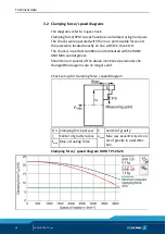
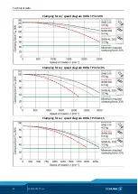
Page 18: ...ith the chuck O D The chuck is in perfect condition and lubricated with SCHUNK LINOMAX special grease Should one or several of the above mentioned parameters be changed the diagrams are no longer valid Chuck set up for clamping force speed diagram F 3 Clamping force per jaw S Center of gravity rs Center of gravity radius amax Max jaw eccentricity of cen ter of gravity in axial direc tion Fmax Max ...

Page 19: ...Technical data 02 00 ROTA TP en 19 Clamping force speed diagram ROTA TP 160 38 Clamping force speed diagram ROTA TP 200 52 Clamping force speed diagram ROTA TP 250 68 ...

Page 20: ...Technical data 20 02 00 ROTA TP en Clamping force speed diagram ROTA TP 315 90 Clamping force speed diagram ROTA TP 315 105 Clamping force speed diagram ROTA TP 350 115 ...

Page 21: ... Mass of chuck jaw set kg sz Safety factor for machining Mc Centrifugal force torque Nm Σs Max clamping force of chuck N kgm 9 81 Nm Calculation of the required clamping force in case of a given rpm The initial clamping force Fsp0 is the total force impacting radially on the workpiece via the jaws due to actuation of the lathe chuck during shutdown Under the influence of rotation the jaw mass gene...

Page 22: ...k piece is released spontaneously Do not exceed the calculated RPM Do not fall below the necessary minimum clamping force Reduction in effective clamping force by the magnitude of the total centrifugal force for gripping from the outside inwards The required effective clamping force for machining Fsp is calculated from the product of the machining force FspZ and the safety factor Sz This factor ta...

Page 23: ...the rpm NOTICE For safety reasons in accordance with DIN EN 1550 the centrif ugal force may be a maximum of 67 of the initial clamping force The formula for the calculation of the total centrifugal force Fc is For this n is the given speed of rotation in RPM The product mB rs is referred to as the centrifugal force torque Mc In case of toolholders with split chuck jaws i e with base jaws and top j...

Page 24: ...vity radius of top jaw rsAB 0 107 m application specific Safety factor Sz 1 5 according to VDI 3106 Safety factor Ssp 1 5 according to VDI 3106 Note Masses of the jaw mounting screws and T nuts are not taken into account First the required effective clamping force Fsp is calculated using the machining force stated Initial clamping force during shutdown Calculation of total centrifugal force For tw...

Page 25: ...ed on the chuck for safety reasons Example of calculation Permissible RPM for a given effective clamping force The following data is known from previous calculations Initial clamping force during shutdown Fsp0 17723 N Machining force for machining job Fspz 3000 N application specific Total centrifugal torque of all jaws Mc 2 668 kgm Safety factor Sz 1 5 according to VDI 3106 Safety factor Ssp 1 5 ...

Page 26: ...ical workpieces or the use of various top jaws as well as uneven application of lub ricants In order to prevent damage resulting from these residual risks the entire rotor is to be dynamically balanced in accordance with DIN ISO 1940 1 Torques per screw Tightening torques for mounting screws used to clamp the chuck on lathes or other suitable technical equipment screw quality 10 9 Screw size M6 M8...

Page 27: ... due to their elasticity are raised from the chuck body by the ventilation of the supply lines and therefore are not subject to wear from the rotating chuck Functional testing Functional test After installation of the chuck its function must be checked prior to start up Two important points are Clamping Force The clamping force of the chuck must be achieved at max operating force pressure Stroke c...

Page 28: ...rface is larger than the surface of the openings Upon pressurization the difference in surface area exerts a radial force on the profile seal in the ring shaped chamber of the distributor ring resulting in optimal static sealing of the profile seal at the air transfer point This allows low loss flow of the air through the openings in the profile seal into the cylinder chamber of the chuck If the s...

Page 29: ...ocking pistons Light mainte nance can be performed on it from the face side of the chuck via a locking screw The locking pistons of the valve unit control the rate of the air that flows to and from the profile seals through two air ducts By changing the pressure of the air at the profile seals the air duct is vented into a cylinder chamber relief chamber on one side During this process the compres...

Page 30: ...ided extended and self locking 10 wedge slant standard wedge hook or base jaw The clamping forces are absorbed by the diameter of the piston collar and braced against by the chuck body Both sides of a piston cover screwed onto the piston neck for clamping and unclamping are pressurized thus causing the piston cover to trigger the axial motion of the piston 4 5 ...

Page 31: ... for I D clamping Moreover no workpieces are allowed to be clamped on the fast jaw stroke since due to the long jaw strokes the resulting clamping forces are lower 1 Please make sure that the entire fast stroke plus at least 1 3 of the clamping stroke corresponding to the basic covering of the TB LH lathe chuck is executed during workpiece clamping 2 4 6 ...

Page 32: ...ed Wear suitable protective equipment CAUTION Risk of injury due to sharp edges and rough or slippery surfaces Wear personal protective equipment particularly protective gloves An eye bolt and an angle are included in the scope of delivery for transporting lathe chucks with a size of 160 and above These chucks are only allowed to be transported on this eye bolt Place the angle under the eye bolt o...

Page 33: ...nd secure against restarting Ensure that no residual energy remains in the system CAUTION Danger of injury due to sharp edges and rough or slippery sur faces Wear personal protective equipment particularly protective gloves NOTICE Always use the correct length of mounting screws when mount ing the chuck and flange Screws that are too long may protrude from the tapping drill hole or damage the mach...

Page 34: ...e head The cylindrical precisely turned centering shoulder on the flange must be screwed on 6 2 mm deep so as to ensure contact with the outer chuck edge In order to avoid a large reach of the chuck the chuck terminating cover having a centering mount can be replaced with one having a short cover for corresponding direct mounting on the spindle nose as per DIN 55027 or Camlock DIN 55029 Of course ...

Page 35: ...n 1 2200 min 1 Two threaded holes are arranged on the circumference at less than 120 from each other and at a distance from the pneumatic connection so that the distributor ring can be secured against turning by means of a set screw belonging to the equipment The set screw is screwed into the threaded hole that brings the pneumatic connections into a suitable position so that the pneumatic supply ...

Page 36: ...t the slotted location is on one of the three bore holes of the dis tributor ring The flat surface of the chuck body which is raised in the area of the distributor ring prevents the penetration of dirt and chips between the distributor ring and the chuck body The hexagon socket screws of the distributor ring should be lightly tightened The two parts of the distributor ring can be realigned with ea...

Page 37: ...nary position the speed can be increased to the value provided in the table below ROTA TP 125 25 TP 160 38 TP 200 55 TP 250 58 TP 315 90 Max rotation speed min 1 4200 4200 3800 3500 2500 a 1 1 1 1 1 5 0 8 1 7 ROTA TP 315 105 TP 350 115 TP LH 315 105 TP LH 350 115 Max rotation speed min 1 3000 2200 2200 2200 a 1 5 6 3 2 ...

Page 38: ... on the rear face side of the distributor ring It must be ensured that the distributor ring is aligned with the chuck body without contact For this mounting type the distributor ring must be equipped with a spacer ring instead of the plastic centering sleeve This spacer ring is loosely enclosed with each ROTA TP TP LH front end power chuck If the distributor ring is to be fastened but is equipped ...

Page 39: ...tween the face side of the headstock and the rear face side of the distributor ring The determined dimension is the height dimension of the spacing consoles In this case the distance dimension a see table above is subtracted If the face side of the headstock is not machined a mean must be determined and any height differences must be compensated by means of a positioning screw or positioning sleev...

Page 40: ...r ring Then they entire assembly group is clamped onto the rigid collar of the machine When mounting the chuck with a bayonet or Camlock the clamping ring should have a cut out to allow access to the collar nuts or clamp ing cams using the corresponding wrench NOTE The distributor ring must be aligned with the outer chuck diameter in such a way that at least a radial and axial run out tolerance of...

Page 41: ... a feeler gauge The air gap between the chuck body and the distributor ring at the front and rear should be uniform over the entire circumference approx 1 mm Additional measurement and alignment can be performed by using a magnetic dial indicator stand which is placed on the face side of the chuck The dial indicator is placed radially against the distributor ring and the distributor ring is aligne...

Page 42: ...Mounting 42 02 00 ROTA TP en A Spacer ring 6 3 3 Page 39 B Centering ring 6 3 2 Page 37 ...

Page 43: ...blocks the pressure toward the outside It is very important that the bore hole of the valve system is lightly lubricated with oil so that the valve system can move easily Too much grease lubrication and dirt in the valve bore hole significantly impair the function of the chuck and should be avoided NOTICE When actuating the clamping device clamping or releasing allow a short pause for ventilation ...

Page 44: ... checked daily and oil must be added if necessary If the oil consumption is too low i e if the oil level does not visibly drop over a period of 2 to 3 days the oil adjustment screw must be opened slightly Depending on the accumulation of condensation the condensation drain screw must be opened occasionally 2 part maintenance unit type WEH with filter oiler and pressure control valve Type WEH 1 ID ...

Page 45: ...ibutor module as accessory with two connections Ø T at front and rear and one already mounted seal plug 6 Semi automatic condensate drain G 1 8 connection Ø W G 1 4 D 84 K 10 Container 7 cl D1 42 K1 28 A 125 E 89 Ø L 4 1 B 213 E1 65 Ø L1 4 5 B1 F 21 M 3 C 42 F1 40 Ø T G 1 8 C1 76 H 215 V G 1 8 C2 61 H1 Weight kg 0 760 weight without pres sure gauge C3 95 J 74 C4 38 J1 110 5 Basic setting for oiler...

Page 46: ...moved on the face side of the chuck The non return valve is removed from the bore hole and the bore hole and the valve are cleaned to remove dirt and any foreign bodies The fine serration of the base jaws and top jaws must be cleaned when the hardened reversible jaws or soft top jaws are adjusted because otherwise the true running accuracy will be reduced Foreign matter such as dust scale casting ...

Page 47: ...mping reserve Hardened reverse jaws may be used only in sets as packaged at the factory since they are ground in sets on the chuck Normally one set of hardened reverse jaws is ordered with the chuck During assembly and disassembly of the reverse jaws numbered 1 to 3 make sure that the single jaws are paired with the base jaws with the same numbers in order to achieve good true running properties T...

Page 48: ...screws item 39 at the chuck mount item 7 screw in 2 screws into the existing threaded holes pushing the mount down 5 Disconnect the spring ring retaining nut item 40 in front of the piston cover item 6 Use the supplied mounting tool item 80 6 Screw in the two hexagon socket head bolts into the existing threaded holes of the piston cover item 6 and pull out the piston cover item 6 7 Chuck with dist...

Page 49: ...ed that the profile seals item 66 be rubbed with grease by hand so that they remain elastic There must be no visible grease residue When the profile seals item 66 are reinsert ed ensure that air passage openings do not align with the pneumatic connections of the distributor ring 13 The cylinder chamber of the chuck must be oiled The jaw guides in the chuck body base jaws and piston at the wedge ho...

Page 50: ... and tighten them alternately 5 Place down the chuck holder with the O rings item 7 52 and screw it with the hexagon socket head screws item 39 6 Lubricate valve system item 18 and valve bore hole with oil install and close with plug in screw and O ring item 3 NOTE All parts of the ROTA TP type front end power chuck are lightweight As such hard hammer blows should never be used during assembly 7 A...

Page 51: ...Designation 1 Chuck body 2 Base jaw 3 Piston with thread 4 Bushing 5 Sealing disk 6 Piston cover 7 Mount 8 T nut 9 Distributor ring 11 Centering ring 12 Spacer ring 13 Locking screw 15 Distributor ring cover 18 Double check valve 34 Set screw DIN 914 35 Screws DIN EN ISO 4762 7984 36 Screws 37 Screws ISO 4762 38 Screws 10 9 DIN EN ISO 4762 109 39 Screws 40 Safety ring Locking nut Screws ROTA TP 31...

Page 52: ...Assembly drawings 52 02 00 ROTA TP en Assembly drawings ROTA TP with standarded cover 9 ...

Page 53: ...Assembly drawings 02 00 ROTA TP en 53 ...

Page 54: ...t into operation until conformity of the ma chine into which the partly completed machine is to be installed with the provisions of the Machinery Directive 2006 42 EC is confirmed Applied harmonized standards especially EN ISO 12100 2010 Safety of machinery General principles for design Risk assessment and risk reduction EN 1550 1997 A1 2008 Machine tools safety Safety requirements for the design ...

Page 55: ...and products X 1 1 4 Lighting X 1 1 5 Design of machinery to facilitate its handling X 1 1 6 Ergonomics X 1 1 7 Operating positions X 1 1 8 Seating X 1 2 Control Systems 1 2 1 Safety and reliability of control systems X 1 2 2 Control devices X 1 2 3 Starting X 1 2 4 Stopping X 1 2 4 1 Normal stop X 1 2 4 2 Operational stop X 1 2 4 3 Emergency stop X 1 2 4 4 Assembly of machinery X 1 2 5 Selection ...

Page 56: ... the machinery X 1 7 1 1 Information and information devices X 1 7 1 2 Warning devices X 1 7 2 Warning of residual risks X 1 7 3 Marking of machinery X 1 7 4 Instructions X 1 7 4 1 General principles for the drafting of instructions X 1 7 4 2 Contents of the instructions X 1 7 4 3 Sales literature X The classification from Annex 1 is to be supplemented from here forward 2 Supplementaryessentialhea...

Reviews: