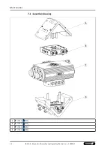
Assembly and settings
28
03.00 | SRH-plus-D | Assembly and Operating Manual | en | 1424337
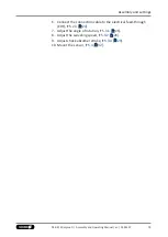
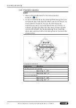
13. Swivel repeatedly to test the setting, readjust if necessary. If
necessary, readjust the swiveling speed and absorber stroke.
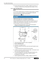
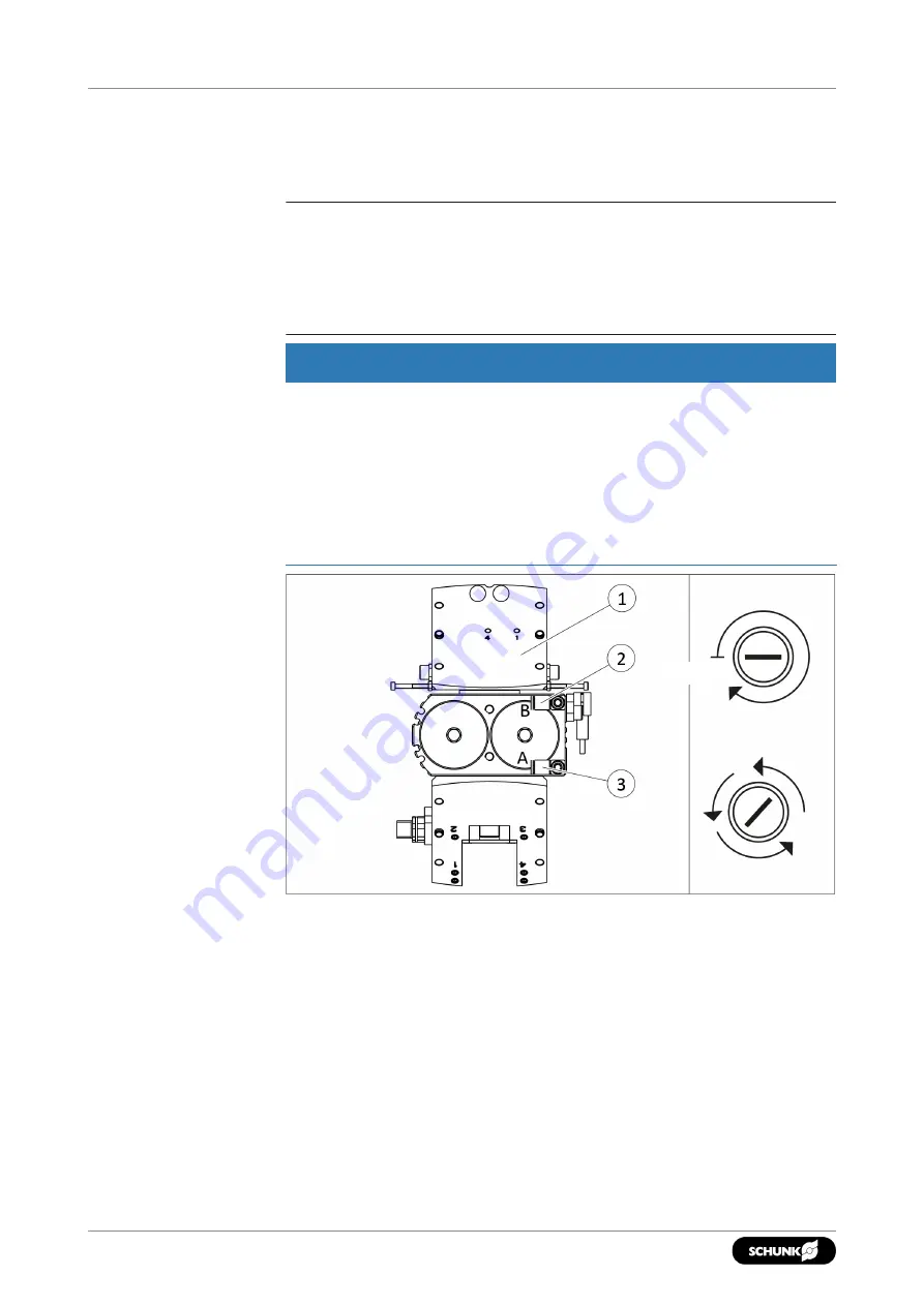
5.3.2 Adjust swiveling speed
NOTE
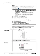
The optimal swiveling speed is achieved by adjusting the swiveling
time on the exhaust air throttles and adjusting the absorber
stroke. Schematic illustration of the optimal
adjustment,
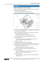
CAUTION
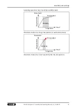
Material damage due to too high swiveling speed!
If the swiveling speed is too high, the assembly will be
decelerated abruptly by the shock absorber and will continue to
oscillate until reaching the end position. This will overload the
shock absorber and may cause damage to it.
•
Adjust the swiveling speed in a way, that the movement
decelerate smoothly in the end position.
closed
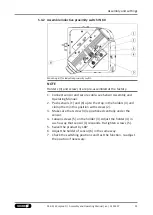
1. Close both exhaust throttle valves completely.
2.
At air connection A (3):
3. Actuate air connection
A
(3).
4. Open the exhaust throttle valve until the swivel head (1) starts
to move.
✓
Swivel head swivels towards the end position.
5. Continue to open the exhaust throttle valve in increments until
the movement decelerates smoothly.
6. If the swiveling speed is too high, the exhaust throttle valve
must be closed again in increments until the optimum
swiveling time is reached.
7. Swivel repeatedly to test the setting, readjust if necessary.


