Assembly and Operating Manual
Pneumatic Swivel Head type SRH
14
Date printed 30.09.11
7.3 Shock absorber use and installation dimensions
SRH
Shock absorber
Specified shock absorber projection (h)
20.1
WP-M 0.25-356
9.5
±0.1
20.2
WP-M 0.25-356
9.5
±0.1
25.1
WP-M 0.25-356
9.5
±0.1
25.2
WP-M 0.25-356
9.5
±0.1
35.1
MC 225 MH2
See measuring
instructions
below
±0.1
35.2
MC 225 MH2
±0.1
40.1
MC 600 MH2
±0.1
40.2
WP-M 1.0-166
17.5
±0.1
50.1
WP-M 1.0-166
17.5
±0.1
50.2
WP-M 1.0-166
17.5
±0.1
60.1
WP-M 1.0-166
17.5
±0.1
60.2
WP-M 1.0-456
17.5
±0.1
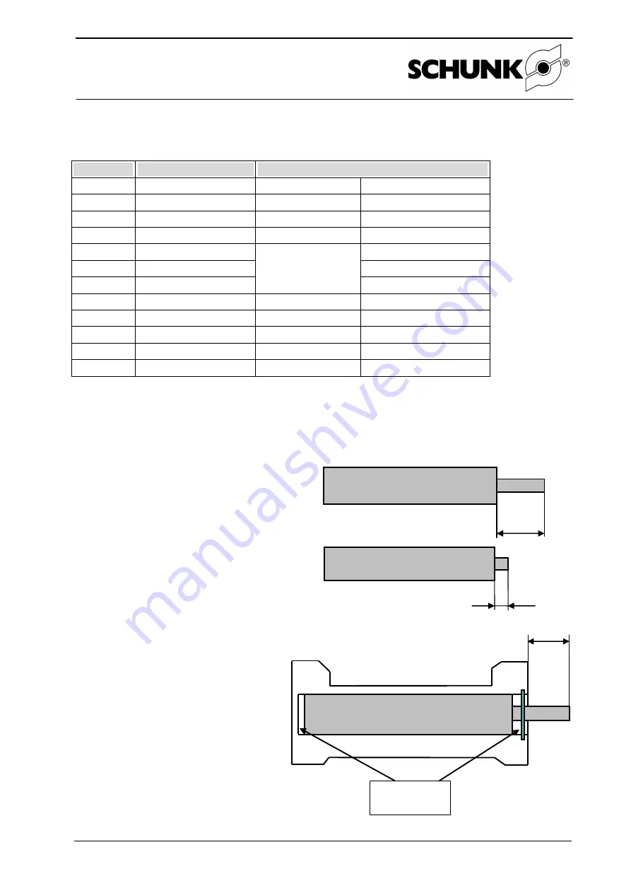
With WP-M shock absorbers, only item 4 of the following measuring instructions has to
be followed. The values specified refer to the shock absorber travel (h).
7.4 Measuring instructions
1. Measure the projection (
x
) of the shock
absorber tappet.
2. Measure the projection (
y
) of the shock
absorber tappet pressed onto the block.
3. Calculate the shock absorber tra-
vel.
h = x - y - 0.2 mm
4. Set the shock absorber
projection (
h
).
x
y
Fitting discs
h


