background image

 
Assembly and Operating Manual 
 
Pneumatic Swivel Head type SRH  


19 

Date printed 30.09.11 

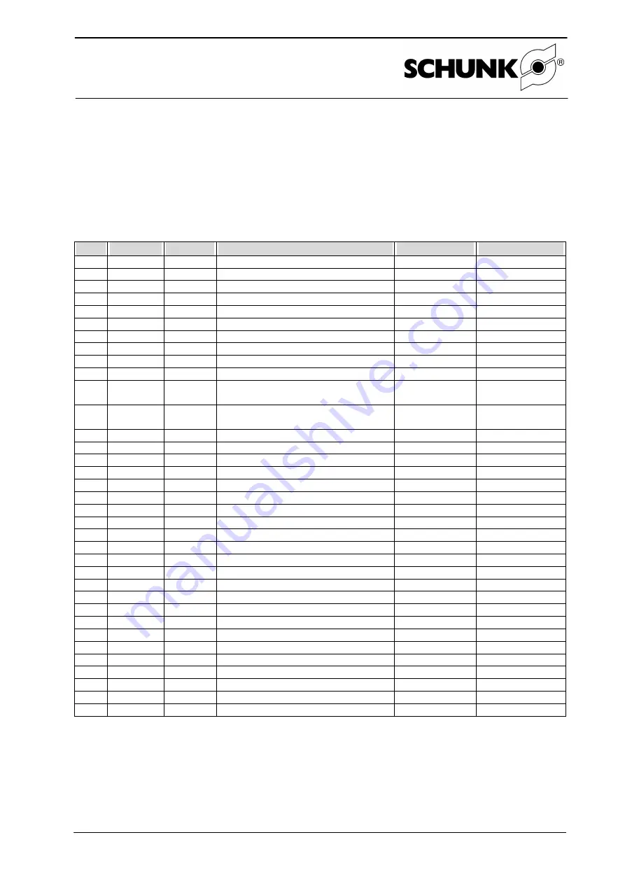
Bills of materials 

9.1  Bills of materials for SRH20 

9.1.1 

SRU bill of materials for SRH20 

Item 

ID 

Quantity  Designation 

Wearing part?  Note 

5513720 

Housing 


5513722 

Guide sleeve 


5513305 

Cover 


5513231 

Adjusting sleeve 90° 


5513229 

Limit sleeve 3° 


5513230 

Stop cover 3° 


19 

5515758 

MDF pinion 


20 

5516177 

MDF flange 


23 

5513266 

Clamping disk 


24 

5513245 

Piston 


31 

9632012 

61805-2RS4 deep groove ball bear-
ing 


32 

9938986 

61803-2RS1 deep groove ball bear-
ing 


33 

9942019 

Set screw DIN913 M4x4 PA 


34 

9942020 

12 

Set screw DIN913 M5x4 PA 


35 

9664003 

Countersunk screw DIN 7991 M6x16 


37 

9664023 

Countersunk screw DIN 7991 M6x25 


39 

9659005 

Locking screw DIN908 M5x5 


40 

9939228 

O-ring DIN3771 Ø23x1.0 


41 

9939230 

O-ring DIN3771 Ø27x1.5 


43 

9611474 

O-ring DIN3771 Ø 26x1.5 


44 

9610009 

Quad ring Ø 15.60x1.78 

Yes 


46 

9936334 

O-ring DIN3771 Ø14x1.5 

Yes 


48 

9939296 

Guide ring Ø20x Ø16x4 

Yes 


49 

9942280 

Safety ring DIN 471 A17x1 


50 

9621025 

Safety ring DIN 472 I14x1 


52 

9936070 

Circular magnet 


54 

9948127 

Shock absorber WP-M 0.35-356 

Yes 


60 

9660424 

Screws DIN912/A2 M3x25 


64 

9941670 


Fitting disk DIN988 7x13x0.15 


65 

9941669 


Fitting disk DIN988 7x13x0.1 


66 

9650414 


Fitting disk DIN988 15x21x0.1 


70 

9939015 

Reducing nipple M5-M5 


72 

9939380 

Centering sleeve Ø12x6.65 


73 

9659003 

Sealing ring M5 


76 

9611063 

O-ring DIN3771 Ø6x1 


Summary of Contents for SRH

Page 1: ...complete satisfaction SCHUNK products are inspiring Our detailed assembly and operation manual will support you Do you have further questions You may contact us at any time even after purchase You can reach us directly at the mentioned addresses in the last chapter of these instructions Kindest Regards Your SCHUNK GmbH Co KG Precision Workholding Systems Bahnhofstr 106 134 D 74348 Lauffen Neckar T...

Page 2: ...VICING INTERVALS 12 7 2 NOTES 12 7 1 DISASSEMBLING THE ROTARY ACTUATOR 13 7 2 REPLACING A SHOCK ABSORBER 13 7 3 SHOCK ABSORBER USE AND INSTALLATION DIMENSIONS 14 7 4 MEASURING INSTRUCTIONS 14 8 ASSEMBLY DRAWINGS 15 8 1 SRU ASSEMBLY DRAWINGS 15 8 2 SRH ASSEMBLY DRAWINGS 17 8 2 1 Exploded view for SRH 20 35 17 8 2 2 Exploded view for SRH 40 60 18 9 BILLS OF MATERIALS 19 9 1 BILLS OF MATERIALS FOR SR...

Page 3: ...inted 30 09 11 9 5 2 EDF bill of materials for SRH50 28 9 6 BILLS OF MATERIALS FOR SRH60 29 9 6 1 SRU bill of materials for SRH60 29 9 6 2 EDF bill of materials for SRH60 30 9 6 3 Bill of materials for SRH60 30 10 TRANSLATION OF ORIGINAL EC DECLARATION OF INCORPORATION 31 ...

Page 4: ...ssumes no liability for any injury or damage resulting from inappropriate use 1 3 Environmental and operating conditions Use the unit only within the application parameters defined in the Technical Catalog The most recent version applies according to the General Terms and Conditions Please make sure that your application has been checked based on the current SCHUNK calculation program If this is n...

Page 5: ...r assembly modification maintenance and adjustment of the unit Carry out all maintenance modifications or attachments outside of the danger zone During installation connection adjusting commissioning and testing measures must be taken to prevent the risk of inadvertent activation of the unit by the fitter or other persons Protective covers must be provided for the use of all handling modules in ac...

Page 6: ... lists see chapter 9 See also our General Terms and Conditions in this regard The unit is considered defective when the basic rotary function is inoperable 3 Scope of delivery The scope of delivery comprises Pneumatic swivel head SRH depending on the version ordered 4 Technical data Please refer to our current catalog for the technical data Please check whether the suitability of your individual a...

Page 7: ...tched off during assembly Please also observe the safety notes in chapter 1 3 5 2 Air connection media connection Pressure medium compressed air Standard for quality of the compressed air according to ISO 8573 1 6 4 4 Open only the required connections and close off those that are not required with dummy stoppers O rings item 84 have been included in the enclosed pack for hose free direct connecti...

Page 8: ...lt in the individual components becoming detached from one another Use a face pin wrench which you position on the axial bores in the stop cover 4 Purge air connection B and apply pressure to air connection A The unit swivels to stop B basic position 180 5 Set the required end position by turning stop B near the domed side of the SRU see above point 3 6 Tighten the screw item 35 SRU 20 40 10 Nm SR...

Page 9: ...t be arrived at gently 4 Retighten the nuts items 101a b Notice The maximum adjustment range of the shock absorbers is 1 5 mm for SRH20 25 0 5 mm for SRH 35 and 3 mm for SRH40 60 Beyond this range leakage commences in order to protect the unit 5 5 Assembling and setting the proximity switches 5 5 1 MMS 22 magnetic switches see data sheet Four grooves have been incorporated in the housing for insta...

Page 10: ... Clamp in this position using the screw item 231 4 Fit the screw item 234 to the distributor plate item 73 and secure with the lock nut item 233 5 Adjust one bracket item 236 so that the sensor responds In order to do this the screws item 231 must be loosened slightly Retighten the screws item 231 when adjustment is complete 6 Swivel the unit 180 7 Adjust the second bracket item 236 so that the se...

Page 11: ...ion SRU 50 8 x M8 Connector for proximity switch connection SRU 50 8 x M12 Connector for proximity switch connection SRU 60 8 x M5 Connector for proximity switch connection SRU 60 8 x M8 Connector for proximity switch connection SRU 60 8 x M12 Connector for proximity switch connection Bending radius Minimum bending radius for continuous movement 10x cable diameter Figure Pin assignment M16 connect...

Page 12: ...he shock absorbers approx million cycles 1 1 1 1 1 0 5 0 5 Environmental temperatures of more than 60 C 140 F can harden the used lubricants faster Therefore lubrication and maintenance works have to be carried out more often 7 2 Notes Please observe the following notes to ensure correct functioning of the rotary actuator 1 Standard for quality of the compressed air according to ISO 8573 1 6 4 4 2...

Page 13: ...ore be checked regularly A shock absorber is functioning cor rectly when the unit hits the end stops gently The shock absorbers are specially tested and can only be obtained from SCHUNK When replacing a shock absorber proceed as follows de pending on which option you have See Figure 1 Figure 5 and Figure 6 1 Undo the screws item 102 and remove the stop cover item 8 11 Remove the safety rings item ...

Page 14: ... 1 MC 600 MH2 0 1 40 2 WP M 1 0 166 17 5 0 1 50 1 WP M 1 0 166 17 5 0 1 50 2 WP M 1 0 166 17 5 0 1 60 1 WP M 1 0 166 17 5 0 1 60 2 WP M 1 0 456 17 5 0 1 With WP M shock absorbers only item 4 of the following measuring instructions has to be followed The values specified refer to the shock absorber travel h 7 4 Measuring instructions 1 Measure the projection x of the shock absorber tappet 2 Measure...

Page 15: ...ssembly and Operating Manual Pneumatic Swivel Head type SRH 15 Date printed 30 09 11 8 Assembly drawings 8 1 SRU assembly drawings Figure 6 Stop side end position adjustability Figure 7 Piston and cover ...

Page 16: ...Assembly and Operating Manual Pneumatic Swivel Head type SRH 16 Date printed 30 09 11 Figure 8 Basic components and media feed through ...

Page 17: ...Assembly and Operating Manual Pneumatic Swivel Head type SRH 17 Date printed 30 09 11 8 2 SRH assembly drawings 8 2 1 Exploded view for SRH 20 35 ...

Page 18: ...Assembly and Operating Manual Pneumatic Swivel Head type SRH 18 Date printed 30 09 11 8 2 2 Exploded view for SRH 40 60 ...

Page 19: ...crew DIN913 M5x4 PA 35 9664003 1 Countersunk screw DIN 7991 M6x16 37 9664023 1 Countersunk screw DIN 7991 M6x25 39 9659005 4 Locking screw DIN908 M5x5 40 9939228 4 O ring DIN3771 Ø23x1 0 41 9939230 4 O ring DIN3771 Ø27x1 5 43 9611474 2 O ring DIN3771 Ø 26x1 5 44 9610009 4 Quad ring Ø 15 60x1 78 Yes 46 9936334 5 O ring DIN3771 Ø14x1 5 Yes 48 9939296 4 Guide ring Ø20x Ø16x4 Yes 49 9942280 1 Safety r...

Page 20: ...3 spacer sleeves self retaining 129 5517075 1 Locking screw M8x0 5 130 9942494 4 M5 screw plug Only for M5 130 9937198 4 M8 screw plug Only for M8 140 9611044 4 O ring Ø10x1 141 9611518 4 O ring Ø2 5x0 5 147 9907474 1 O ring Ø22x1 148 9941190 1 Nut M18x0 75 9 1 3 Bill of materials for SRH20 Item ID Quantity Designation Wearing part Note 4 5516189 1 Swivel head 77 5516188 1 Screw on bracket 78 5517...

Page 21: ... 9611053 4 O ring DIN3771 Ø35x1 5 43 9936055 2 O ring DIN3771 Ø32x1 5 44 9937411 4 Cylinder seal Ø25xØ19x3 25 Yes 46 9936334 5 O ring DIN3771 Ø14x1 5 Yes 48 9939297 4 Guide ring Ø25xØ21x4 Yes 49 9942280 1 Safety ring DIN 471 A17x1 50 9621025 2 Safety ring DIN 472 I14x1 52 9937285 2 Circular magnet Ø5x3 54 9948128 2 Shock absorber WP M 0 35 456 Yes 60 9660424 2 Screws DIN912 A2 M3x25 64 9941670 Fit...

Page 22: ...r M5 130 9937198 4 M8 screw plug Only for M8 140 9611044 4 O ring Ø10x1 141 9611518 4 O ring Ø2 5x0 5 147 9907474 1 O ring Ø22x1 148 9941190 1 Nut M18x0 75 9 2 3 Bill of materials for SRH25 Item ID Quantity Designation Wearing part Note 4 5516189 1 Swivel head 77 5516188 1 Screw on bracket 78 5517021 1 SRH cover plate 88 5515921 1 plug angle 108 9664501 2 Countersunk screw M3 x 8 115 9662006 2 Scr...

Page 23: ... screw DIN913 M5x4 PA 35 9664003 1 Countersunk screw DIN 7991 M6x16 37 9664023 1 Countersunk screw DIN 7991 M6x25 39 9659005 4 Locking screw DIN908 M5x5 40 9939231 4 O ring DIN3771 Ø38x1 5 41 9611052 4 O ring DIN3771 Ø45x1 5 43 9907131 2 O ring DIN3771 Ø42x1 5 44 9938989 4 Cylinder seal Ø35xØ27x3 25 Yes 46 9900286 5 O ring DIN3771 Ø17x1 5 Yes 48 9939298 4 Guide ring Ø35xØ31x4 Yes 49 9907493 1 Safe...

Page 24: ... 9941766 1 EDF connection circuit board 25 127 9942114 4 M3 spacer sleeves self retaining 129 5517075 1 Locking screw M8x0 5 130 9942494 4 M5 screw plug Only for M5 130 9937198 4 M8 screw plug Only for M8 140 9611044 4 O ring Ø10x1 141 9611518 4 O ring Ø2 5x0 5 147 9907474 1 O ring Ø22x1 148 9941190 1 Nut M18x0 75 9 3 3 Bill of materials for SRH35 Item ID Quantity Designation Wearing part Note 4 5...

Page 25: ...rew DIN913 M5x4 PA 35 9664003 1 Countersunk screw DIN 7991 M6x16 37 9939511 1 Countersunk screw DIN 7991 M6x30 39 9659001 4 Locking screw DIN908 G1 8 40 9611101 4 O ring DIN3771 Ø43x1 5 41 9611118 4 O ring DIN3771 Ø50x1 5 43 9939154 2 O ring DIN3771 Ø48x1 5 44 9907470 4 Cylinder seal Ø40xØ32x3 25 Yes 46 9611066 5 O ring DIN3771 Ø23x1 5 Yes 48 9939003 4 Guide ring Ø40xØ36 92x4 Yes 49 9620002 1 Safe...

Page 26: ... Reducer M8x0 5 M5x0 5 Only for M5 125 9941787 8 Reducer PG9 M8x0 5 Only for M8 M5 126 9941767 1 EDF connection circuit board 40 127 9942114 4 M3 spacer sleeves self retaining 129 5517075 1 Locking screw M8x0 5 130 9942494 8 M5 screw plug Only for M5 130 9937198 8 M8 screw plug Only for M8 140 9611076 4 O ring Ø12 x 1 141 9611300 4 O ring Ø3 5 x 1 147 9907474 1 O ring Ø22x1 148 9941190 1 Nut M18x0...

Page 27: ...M6x6 PA 35 9682117 1 Countersunk screw DIN 7991 M8x25 37 9939010 1 Countersunk screw DIN 7991 M8x30 39 9659001 4 Locking screw DIN908 G1 8 40 9937019 4 O ring DIN3771 Ø54 x 1 41 9935467 4 O ring DIN3771 Ø61 x 1 5 43 9638388 2 O ring DIN3771 Ø56 x 1 5 44 9935507 4 Cylinder seal Ø50xØ42x3 25 Yes 46 9611143 9 O ring DIN3771 Ø25 x 1 5 Yes 48 9939295 4 Guide ring Ø50xØ46 9x4 Yes 49 9936698 1 Safety rin...

Page 28: ...87 8 Reducer PG9 M8x0 5 Only for M8 M5 126 9941767 1 EDF connection circuit board 40 127 9942114 4 M3 spacer sleeves self retaining 129 5517075 1 Locking screw M8x0 5 130 9942494 8 M5 screw plug Only for M5 130 9937198 8 M8 screw plug Only for M8 130 9905303 8 Screw plug M12 Only for M12 140 9611076 4 O ring Ø14 x 1 141 9941243 4 O ring Ø3 5 x 0 5 147 9907474 1 O ring Ø22x1 148 9941190 1 Nut M18x0...

Page 29: ...6 PA 35 9682117 1 Countersunk screw DIN 7991 M8x25 37 9939010 1 Countersunk screw DIN 7991 M8x30 39 9659001 4 Locking screw DIN908 G1 8 40 9939232 4 O ring DIN3771 Ø65 x 1 5 41 9611117 4 O ring DIN3771 Ø74 x 1 5 43 9935792 2 O ring DIN3771 Ø71 5 x 1 5 44 9938990 4 Cylinder seal Ø60xØ52x3 25 Yes 46 9611143 9 O ring DIN3771 Ø25 x 1 5 Yes 48 9939004 4 Guide ring Ø60xØ56 92x4 Yes 49 9936698 1 Safety r...

Page 30: ...87 8 Reducer PG9 M8x0 5 Only for M8 M5 126 9941767 1 EDF connection circuit board 40 127 9942114 4 M3 spacer sleeves self retaining 129 5517075 1 Locking screw M8x0 5 130 9942494 8 M5 screw plug Only for M5 130 9937198 8 M8 screw plug Only for M8 130 9905303 8 M12 screw plug Only for M12 140 9611076 4 O ring Ø14 x 1 141 9941243 4 O ring Ø3 5 x 0 5 147 9907474 1 O ring Ø22x1 148 9941190 1 Nut M18x0...

Page 31: ...il conformity of the machine into which the incomplete machine is to be installed with the provisions of the Machinery Directive 2006 42 EC is confirmed Applied harmonized standards especially EN ISO 12100 1 Safety of machines Basic concepts general principles for design Part 1 Basic terminology methodology EN ISO 12100 2 Safety of machines Basic concepts general principles for design Part 2 Techn...

Page 32: ...Assembly and Operating Manual Pneumatic Swivel Head type SRH 32 Date printed 30 09 11 ...

Reviews: