


Assembly and Operating Manual
Pneumatic Swivel Head type SRH
9
Date printed 30.09.11
5.4 Fine adjustment of shock absorber travel
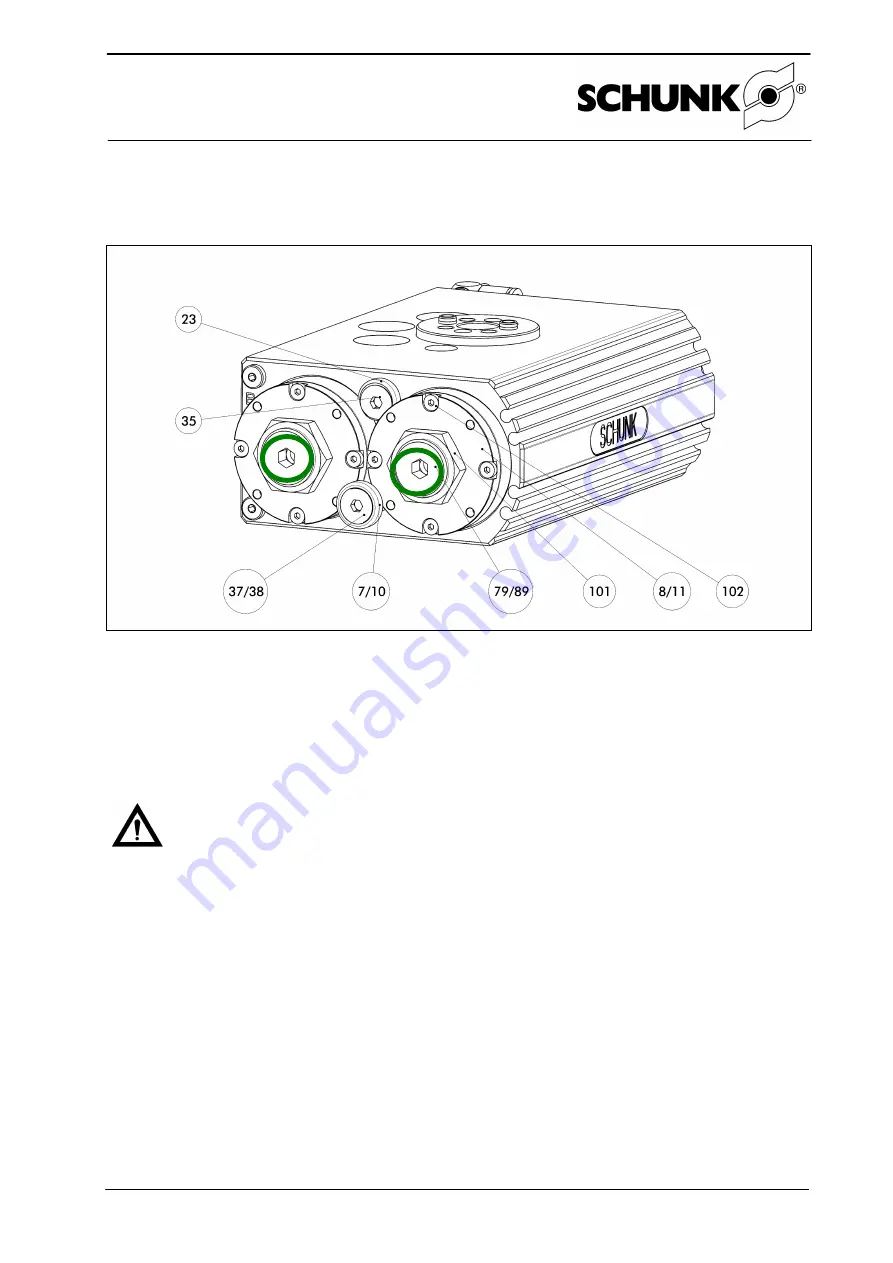
Figure Fine adjustment of shock absorber travel
1. To adjust the cushioning in the end position, loosen the nut (item 101) at stop A/ B using an
open-end wrench while bracing the striker pin (item 79/ 89) with a hexagon socket wrench.
2. Unscrewing the striker pin shortens the shock absorber travel by 1.5 mm per revolution.
3. Swivel the loaded unit to check the cushioning effect.
The end positions must be arrived at gently.
4. Retighten the nuts (items 101a / b).
Notice!
The maximum adjustment range of the shock absorbers is 1.5 mm for SRH20+25,
0.5 mm for SRH 35 and 3 mm for SRH40-60.
Beyond this range, leakage commences in order to protect the unit.
5.5
Assembling and setting the proximity switches
5.5.1
MMS 22 magnetic switches (see data sheet)
Four grooves have been incorporated in the housing for installing the magnetic switches. Pro-
ceed as follows to set a switching position:
1. Insert the magnetic switch into the groove.
2. Move it along the groove until the switch actuates.
3. Fix the magnetic switch in place in accordance with the supplied data sheet.
4. Check that the setting is correct by swiveling the unit several times.


