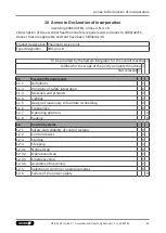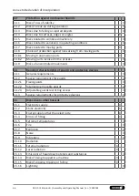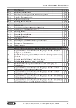
Maintenance
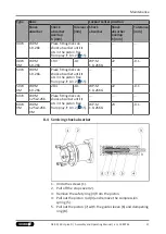
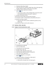
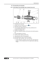
11. Screw on stop cover (7) again.
12. Proceed analogously for the second shock absorber.
13. If necessary, adjust the shock absorber,
.
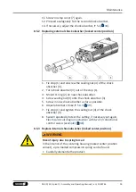
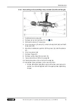
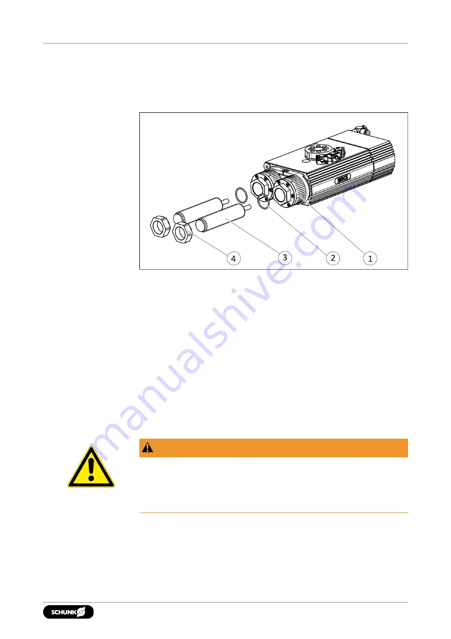
8.5.2 Replacing external shock absorber (locked center position)
1. Fix stop (1) and unscrew the sealing nut (4) of the shock
absorber (3).
2. Turn shock absorber (3) out of the stop (1).
3. Mount O-ring (2) on new shock absorber.
4. Screw sealing nut (4) onto the shock absorber (3)
5. Screw in new shock absorber as far as possible.
6. Adjust absorber stroke,
.
7. Fix stop (1) and tighten the sealing nut (4) of the shock
absorber (3).
8. Swivel repeatedly to test the setting, if necessary set again,
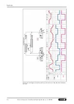
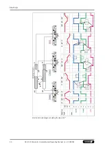
Electrical circuit diagram actuation with two 5/3 directional
control valves (example) [
.
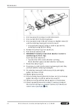
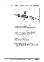
8.5.3 Replace internal shock absorber (locked center position)
WARNING
Risk of injury due to spring forces!
In the interior of the centering housing (locked center position
variant), a pre-loaded compression spring can be found.
•
Carefully dismantle the product.
59
04.00 | SRU-plus-D | Assembly and Operating Manual | en | 1380765
Summary of Contents for SRU-plus-D
Page 1: ...Original Operating Manual Assembly and Operating Manual SRU plus D Pneumatic swivel unit ...
Page 68: ...68 04 00 SRU plus D Assembly and Operating Manual en 1380765 ...
Page 69: ......
Page 70: ......
Page 71: ......

