Maintenance
60
04.00 | SRU-plus-D | Assembly and Operating Manual | en | 1380765
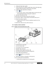
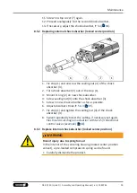
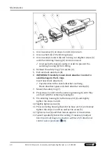
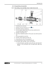
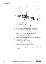
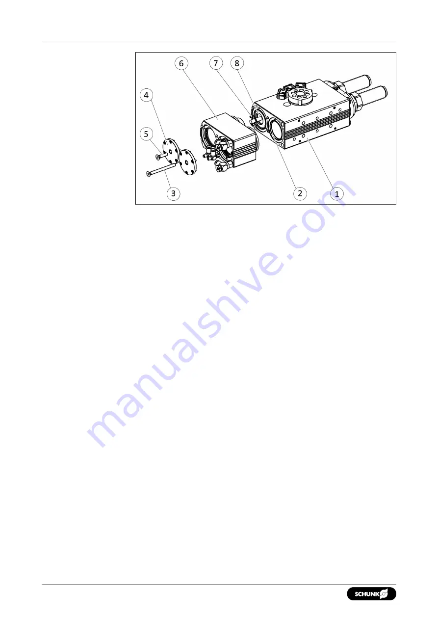
1. Unscrew screw (5) on stops
C
and
D
(4) one turn.
2. Unscrew bolt (3) of the limiting sleeve.
3. Unscrew stops C and D (8) and in doing so retighten screw (3)
until the centering housing (6) can be removed.
✓
Unscrew both stops (4) evenly in order to prevent the
centering housing (6) from tilting.
4. Remove the safety ring (7) on piston (2).
5. Pull out shock absorbers (8).
6.
IMPORTANT! Carefully mount shock absorber in order to
avoid damage to the O-rings.
Insert new shock absorbers.
✓
Pay attention to the shock absorber overhang,
Shock absorber types and shock absorber overlap (h).
7. Mount the safety ring (7).
8. Press stops
C
and
D
into the centering housing (6) until they
are flush with the centering housing (6).
9. Fit centering housing (6) to the base unit (1) and slightly
tighten the stops
C
and
D
.
10. Slightly tighten screw (3).
11. Press centering housing (6) onto the base unit (1) and evenly
tighten the stops
C
and
D
as well as the screw (5).
12. Tighten screw (3) and then loosen approx. 1/4 revolution.
13. Swivel repeatedly to test the setting, if necessary readjust
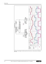
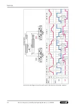
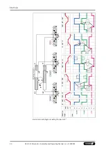
Electrical circuit diagram actuation with two 5/3 directional
control valves (example) [
.
Summary of Contents for SRU-plus-D
Page 1: ...Original Operating Manual Assembly and Operating Manual SRU plus D Pneumatic swivel unit ...
Page 68: ...68 04 00 SRU plus D Assembly and Operating Manual en 1380765 ...
Page 69: ......
Page 70: ......
Page 71: ......

