Assembly
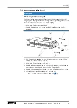
5.5 Mounting inductive proximity switch IN 80
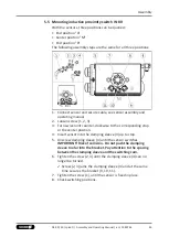
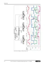
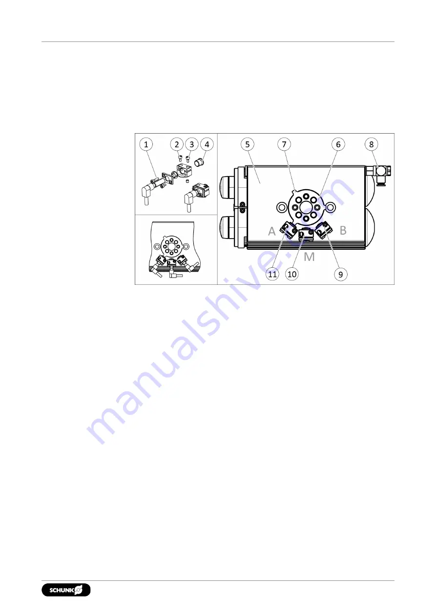
With the sensors, three positions can be queried:
• End position "A"
• Center position "M"
• End position "B"
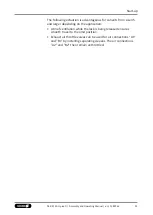
The following assembly steps are the same for all three positions:
1. Connect sensor and secure cable, see sensor assembly and
operating manual.
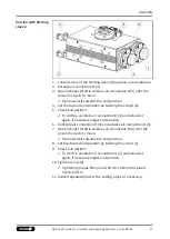
2. Loosen screw (1, 2, 3).
3. Turn swivel unit counter-clockwise to the corresponding stop
or the center position.
4. Insert sensor into the clamping sleeve (4) up to stop.
5. Unscrew clamping sleeve (4) until the sensor switches.
IMPORTANT! Risk of collision - Do not push the clamping
sleeve too far into the bracket. Pay attention to the spacing
between the clamping sleeve and the switching cam.
6. Tighten the screw (2, 3) until the clamping sleeve (4) can no
longer be turned.
✓
Screw (2, 3) jams the clamping sleeve (4) and at the same
time secures the bracket (9, 10, 11).
7. Tighten the screw (1), until the sensor is fixed in place.
8. Check switching positions.
43
04.00 | SRU-plus-D | Assembly and Operating Manual | en | 1380765
Summary of Contents for SRU-plus-D
Page 1: ...Original Operating Manual Assembly and Operating Manual SRU plus D Pneumatic swivel unit ...
Page 68: ...68 04 00 SRU plus D Assembly and Operating Manual en 1380765 ...
Page 69: ......
Page 70: ......
Page 71: ......

