Product description
02.00 | SWS-L | Assembly and operating manual | en | 0389037
13
4 Product description
4.1 Quick-change head (SWK-L)
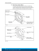
The Quick-change head (SWK-L) includes an anodized aluminum
body, a hardened stainless-steel locking mechanism, and hardened
steel alignment pins (see Figure).
The SWK-L plate has 4 (SWK-L-1210 Series: 6) flat sides for mount-
ing of optional modules. Flat ‘A’ is dedicated for mounting of the
control/signal module along with SWK-L supply air that is provided
through an air or valve adapter. Flats ‘B’, ‘C’, and ‘D’ (SWS-L-1210
Series and ‘F’) are fully interchangeable and optional modules can
be arranged to suit the application or robot dress as required.
The locking mechanism consists of a cylindrical housing with holes
that retain hardened chrome-steel balls. Tapered pins located on
the SWK-L mate with holes in the SWA-L to ensure repeatable
alignment during the coupling process. An extreme pressure
grease is applied to the cam, male coupling, ball bearings and
alignment pins to enhance performance and maximize life of the
components.
SWK-L-210:
A dual-sensor assembly is mounted into the body of
the SWK-L to verify the lock/unlock position of the piston and cam.
The sensors provide the lock and unlock (L/U) signals through the
control/signal module.
SWK-L-310 and 510:
Proximity sensors are designed into the body
of the SWK-L to verify the lock/unlock position of the piston and
cam. The sensors provide the lock and unlock (L/U) signals through
the control/signal module.
SWK-L-1210:
The SWK-L is comprised of 3 locking mechanisms.
Each locking mechanism consists of a cam, male coupling, and
chrome-steel balls. Tapered pins located on the SWK-L mate with
holes in the SWA-L to ensure repeatable alignment during the
coupling process. Extreme pressure grease is applied to the cams,
male couplings, ball bearings, and pins to enhance performance
and maximize the life of the SWK-L.
Proximity sensors (6 total) are designed into the body of the SWK-L
to verify the locked/unlocked position of each locking mechanism.
Due to the multiple locking mechanism design, the proximity
sensors are grouped such that 3 sensors are for Lock and 3 are for
Unlock. The Lock/Unlock signal at each locking mechanism is
routed to the signal junction module. The junction module
provides the control/signal module with the Lock/Unlock state of
the SWK-L. See the cable routing illustrations in chapter "Installa-
tion" to understand the relationship between the sensors, junction
module and control module.)


