Installation
24
02.00 | SWS-L | Assembly and operating manual | en | 0389037
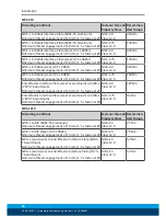
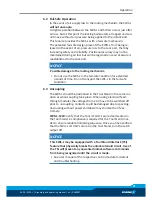
Lock-up should occur with the SWK-L in the No-Touch™ locking
zone (see following table), but not touching the SWK-L. As locking
occurs, theSWK-L should draw the SWA-L into the locked position.
Tool Stands may also need to incorporate means for covering tools
and electrical modules to protect them in dirty environments, such
as grinding or welding. Alternatively, locating Tool Stands in areas
shielded from weld spatter, fluids, adhesives, or other debris
would eliminate the need for tool covers.
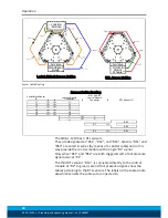
SWK-L
SWA-L
Twisting
Cocking Offset
(About X and Y)
X, Y and Z Offset
Offset Definitions
Maximum Recommended Offsets Prior to Coupling
Model
No-Touch™ Zone Z
Offset (Max)* (mm)
X and Y Offset (Max)**
(mm)
Cocking Offset (Max)
(degrees)
SWS-L-210
2.5
±2
±1
SWS-L-310
2.5
±2
±1
SWS-L-510
2.5
±2
±1
SWS-L-1210
1
±2
±1
* Maximum values shown. Decreasing actual values will minimize wear during coupling/
uncoupling.
** Actual allowable values may be higher in some cases but higher offsets will increase
wear during coupling.

