background image

Troubleshooting

34

02.00 | SWS-L | Assembly and operating manual | en | 0389037

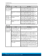
Symptom

Cause

Resolution

R2 input (RS3
sensor) not on.

SWK-L not in position at
Pickup.

Reprogram pick-up point so SWK-L and SWA-L
are parallel and within 1 mm of each other.

Sensor/cable damage.

Check the RS3 sensor face for damage. Replace
if necessary.
Check cable between RS3 sensor and the R2
connector at control module for damage and
replace as needed.

Summary of Contents for SWS-L

Page 1: ...Original manual Assembly and operating manual SWS L Heavy Load Change System...

Page 2: ...rations for the purpose of technical improvement Document number 0389037 Version 02 00 12 11 2018 en SCHUNK GmbH Co KG All rights reserved Dear Customer thank you for trusting our products and our fam...

Page 3: ...hange head SWK L 13 4 2 Quick Change Adapter SWA L 16 4 3 Optional Modules 18 5 Installation 19 5 1 SWK L 21 5 2 SWA L 22 5 3 Tool Stand Design 23 6 Operation 25 6 1 Coupling Sequence 25 6 2 Fail Safe...

Page 4: ...1 SWS L 210 51 8 3 2 SWS L 310 51 8 3 3 SWS L 510 51 8 3 4 SWS L 1210 51 8 4 Assembly drawings 52 8 4 1 SWS L 210 52 8 4 2 SWS L 310 54 8 4 3 SWS L 510 56 8 4 4 SWS L 1210 58 9 Translation of original...

Page 5: ...is manual Illustrations in this manual are provided for basic understanding and may differ from the actual product design In addition to these instructions the documents listed under Ap plicable docum...

Page 6: ...uct is used as intended the warranty is valid for 24 months from the ex works delivery date under the following con ditions Observe the specified maintenance and lubrication intervals Observe the ambi...

Page 7: ...cation parameters The product is intended for industrial use 2 2 Not intended use It is not intended use if the product is used for example as a pressing tool stamping tool lifting gear guide for tool...

Page 8: ...tasks recognize and avoid possible dangers and knows the relevant standards and reg ulations Instructed person Instructed persons were instructed by the operator about the del egated tasks and possib...

Page 9: ...ent of the machine sys tem Switch off the energy supply WARNING Remove all temporary protective materials caps plugs tape etc on locking face of Tool Changer and modules prior to oper ation Failure to...

Page 10: ...WARNING Using the Tool Changer in applications other than intended will result in damage to Tool Changer modules or end of arm tool ing and could cause injury to personnel The Tool Changer is only to...

Page 11: ...700 16 200 Z Torsion 6 900 9 600 10 500 16 200 Positional Repeatab ility mm Repeatabilitytestedatrated loadatonemillioncycles 0 015 Weight kg coupled nomodules Total 8 2 20 4 28 28 SWK L 5 4 12 7 19 3...

Page 12: ...echanism position Internal proximity sensors 6 with cable and connector to indic ate locking mechanism position RTL Ready To Lock Flat Pack proximity sensor with cable and connector for direct wir ing...

Page 13: ...ock position of the piston and cam The sensors provide the lock and unlock L U signals through the control signal module SWK L 310 and 510 Proximity sensors are designed into the body of the SWK L to...

Page 14: ...Retaining Tabs Common Ledge Feature For Modul Mounting Flats B C and D Internal Prox Sensors Lock Unlock Not Visible Prox Sensor Location RTL Signal SWK L 210 Prox Sensor RTL Signal Ball Bearing 9x Ca...

Page 15: ...l Bearings 12x Common ledge mounting feature 3x Internal Lock Unlock sensors Not visible SWK L 510 Ball Bearings 36x Cam Alignment Pin Proximity Sensor RTL Signal Lock Unlock Air Supplied through Air...

Page 16: ...SWS L 1210 3 hardened stainless steel bearing races The SWA L has 4 SWS L 1210 6 flat sides for mounting of optional modules Alignment Pin Bushing 2x Bearing Race Prox Sensor Target RTL Prox Sensor Ta...

Page 17: ...n 2x RTL Sensor Target 2x SWA L Body Bearing Race Common Ledge Mounting Feature 4x SWAS L 510 Proximity Sensor Target RTL Alignment Pin Bushing Proximity Sensor Target RTL Bearing Race Junction Module...

Page 18: ...ules for flats B C or D SWS 1210 or F are interchangeable to suit the application or the dress out required The optional modules are mounted to the SWK L or SWA L using a common ledge mounting feature...

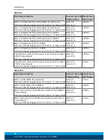
Page 19: ...18 mm 1 5 x fastener M12 1 75 Class 12 9 94 Nm SWS 310 Mounting conditions Fastener Size and Property Class Recommen ded Torque SWK L to Robot Interface Plate 6061 T6 aluminum Minimum thread engagemen...

Page 20: ...bot steel USS 90KSI Minimum thread engagement of 12 mm 1 0 x fastener M12 1 75 Class 12 9 135 Nm End effector Interface Plate steel or aluminum to SWA L 7075 T6 aluminum Minimum thread engagement of 2...

Page 21: ...IPs are available upon request Mounting Fastenres and Dowel Pin Customer Supplied Tool Interface Plate Fasteners and Dowel Pins Customer Supplied Robot Arm SWK L SWA L Typical Installation SWS L 210 3...

Page 22: ...ot exceed 6 3mm If necessary the race cover can be removed to allow for addi tional boss height The thickness of the interface plate must be great enough to provide the necessary thread engagement for...

Page 23: ...up These high forces can cause excessive wear and even jamming of the end effector and robot The degree of float required depends on the accuracy of the robot s positioning and the repeatability of t...

Page 24: ...ely locating Tool Stands in areas shielded from weld spatter fluids adhesives or other debris would eliminate the need for tool covers SWK L SWA L Twisting Cocking Offset About X and Y X Y and Z Offse...

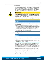
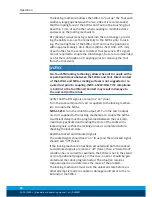
Page 25: ...ubrication Adjustment and Replacement Tubes of lubricant for this purpose are shipped with every SWS L Note MobilGrease XHP222 Special is a NLGI 2 lithium com plex grease with molybdenum disulfide 6 1...

Page 26: ...upling SWS L 1210 ONLY if Z compliance is built in to the Tool Stand Contact may result in damage to the unit and or the robot Verify that the RTL signals are read as on true Turn the Lock command on...

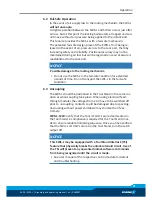
Page 27: ...ondition for extended periods of time Do not transport the SWS L in the fail safe condition 6 3 Uncoupling The SWS L should be positioned in the Tool Stand in the same loc ation as when coupling took...

Page 28: ...Lock Unlock sig nals so that the coupling process is completed before checking the Locked state Read the Locked and Unlocked signals The Unlock signal should read on true and the Lock signal should re...

Page 29: ...L1 Flat A Control Module U3 RS3 L3 Lock and Unlock sensors L2 and U2 not visible in this view Inside the junction module all 3 Lock sensors are wired in series which provides for one Locked signal via...

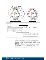
Page 30: ...ol Module Connector 1 2 RS1 RS2 RS3 RTL Sensor ID The SWK L 1210 has 3 RTL sensors They are designated as RS1 RS2 and RS3 Sensors RS1 and RS2 are wired in series by means of a splitter cable and in th...

Page 31: ...Tool Stand Re teach the robot to bring the SWK L and SWA L closer together prior to attempting to lock Ready To Lock RTL sensors not activated in dicating Tool is not posi tioned properly Check that t...

Page 32: ...ing Sensor Assemblies Replace the unlock sensor sub assembly as necessary SWS L 1210 Symptom Cause Resolution Unit will not Lock or Unlock or the locking mechanisms are jammed The ball bearings and or...

Page 33: ...ge Check LED light on each of the three Unlock sensors If OFF check for cable damage and a secure connection to the junction module Replace sensor and or cable as needed Main Unlock sensor cable damag...

Page 34: ...ensor not on SWK L not in position at Pickup Reprogram pick up point so SWK L and SWA L are parallel and within 1 mm of each other Sensor cable damage Check the RS3 sensor face for damage Replace if n...

Page 35: ...e unit Require ments of the storage magazine 8 1 Preventive Maintenance The Tool Changer and optional modules are designed to provide a long life with regular maintenance A visual inspection and preve...

Page 36: ...n bushing wear may be an indication of poor robot position during pickup drop off Adjust robot position as needed Check Tool Stand for wear and alignment problems Wear on the balls bearing race could...

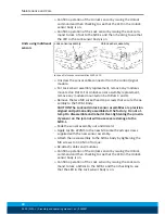
Page 37: ...s Cleaning balls and outer surfaces of male coupling Cleaning balls cam an inner surfaces of male coupling The locking mechanism must be in the unlock state before cleaning Use a clean rag to thorough...

Page 38: ...lubricant to the balls the male coup ling inside and out and the alignment pins 8 2 1 2 Cleaning the Bearing Race and Alignment Pin Bushings SWA 1 Use a clean rag to thoroughly remove any lubricant a...

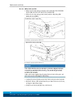
Page 39: ...ontrol signal module If present remove the module s on the flat D Remove the two M3 socket head cap screws that secure the as sembly to the SWK L body Slide the sensor assembly out and discard Visuall...

Page 40: ...both Flats C and D Remove the two M4 socket head cap screws that secure the as sembly to the SWK L Body CAUTION The Lock and Unlock sensor assemblies are precision aligned and permanently assembled at...

Page 41: ...bly NOTICE The Lock and Unlock sensor assemblies are precision aligned and permanently assembled at the factory Do not attempt to disassembled and re build 5 Apply Loctite 222MS to the new M3 socket h...

Page 42: ...r assembly SWS L 310 Lock Unlock sensor assembly Lock Unlock sensor assembly SWS L 510 NOTICE The Lock Unlock sensor assembly is precision aligned and per manently assembled at the factory Do not atte...

Page 43: ...Assemblies SWS L 1210 NOTICE The Lock and Unlock sensor assemblies are precision aligned and per manently assembled at the factory Do not attempt to adjust the po sition of the sensor or severe damage...

Page 44: ...he proximity sensor or the jam nut will cause severe damage to the SWK L NOTE When adjusting the lock sensor the SWK L must be locked to the Tool When adjusting the unlock sensor the SWK L must be sep...

Page 45: ...om the EOAT When adjusting the lock sensor the SWK L must be locked to the Tool When adjusting the unlock sensor the SWK L must be separated from the Tool and in the unlocked condition Unlock sensor J...

Page 46: ...of the new sensor by bringing a metallic ob ject into close proximity to the face of the sensor and watching for the LED in the body of the sensor to come on RTL Sensor Replacement 8mm Threaded Barre...

Page 47: ...body 3 Remove the sensor from the SWK L and discard 4 Screw the new sensor into the SWK L body until the face of the sensor is flush with the surrounding face of the SWK L body Use a socket and a tor...

Page 48: ...of the sensor is flush with the surrounding face of the SWK L body Turn the sensor back turn Use a crowfoot and a torque wrench to tighten the jam nut to 2 26 Nm of torque Replace the sensor cable if...

Page 49: ...ng the Alignment Pin 4mm Hex Key 4mm Hex Key SWS L 210 510 Unscrew the alignment pin sub assembly from the SWK L using a 4mm hex key see Figure above Note If for any reason the pin cannot be removed u...

Page 50: ...grease to the Alignment Pin Cleaning and Lubrication of the Locking Mechanism 8 2 5 2 SWS L 1210 1 1 8 Two Piece Pin Sub Assembly Unscrew the alignment pin sub assembly from the SWK L using a 5mm hex...

Page 51: ...ion SWK L Complete SWK L 310 No Options SWA L Complete SWA L 310 No Options Other Sensors 1x Set 2x RTL 3x Cables with connectors 0 33m 1x Cable with connector 0 4m Alignment Pin 2x Alignment Pin 8 3...

Page 52: ...SWA L B C 160 Flat A 12 Slip Fit 12 Dp Customer Interface with air block spacer installed Tool Cover 10 Slip Fit 12 Dp Customer Interface 30 6 Tapped M10X1 5 20 Dp Equally Spaced Customer Interface Fl...

Page 53: ...Maintenance and Care 02 00 SWS L Assembly and operating manual en 0389037 53 SWK L 210 Master Assembly SWK L 310 SWA L 210 Tool Assembly SWA L 210...

Page 54: ...able 1 for Thread Depth Equally Spaced Customer Interface Flat A Tool Cover B C 200 B C 160 125 H7 5 Dp See Note 3 Customer Interface Flat D 2 10 Slip Fit 16 Dp Equally Spaced Customer Interface 45 Fl...

Page 55: ...Maintenance and Care 02 00 SWS L Assembly and operating manual en 0389037 55 SWK L 310 Master Assembly SWK L 310 SWA L 310 Tool Assembly SWA L 310...

Page 56: ...125 Slip fit Customer Interface 6 4 Boss 54 7 Pin 5 57 141 5 Coupled 82 7 SWK L 58 8 SWA L B A 30 Typ 15 5 Tapped M12x1 75 29 Dp Equally Spaced Counter Clockwise Customer Interface Flat A 12 Tapped M1...

Page 57: ...Maintenance and Care 02 00 SWS L Assembly and operating manual en 0389037 57 SWK L 510 Master Assembly SWK L 510 SWA L 510 Tool Assembly SWA L 510...

Page 58: ...de View Uncoupled SWK L Side projection only 81 3 35 6 B C 91 3 Places Customer Interface 12 C Bored 41 9 Dp From Far Side For M10 SHCS Equally Spaced Pattern 3 Places Customer Interface 15 8 4 SWA L...

Page 59: ...Maintenance and Care 02 00 SWS L Assembly and operating manual en 0389037 59 SWK L 1210 Master Assembly SWK L 1210 SWA L 1210 Tool Assembly SWA L 1210...

Page 60: ...ration is rendered invalid if modifications are made to the product Product designation Heavy Load Change System SWS L The partly completed machine may not be put into operation until conformity of th...

Page 61: ...ntegration X 1 1 3 Materials and products X 1 1 4 Lighting X 1 1 5 Design of machinery to facilitate its handling X 1 1 6 Ergonomics X 1 1 7 Operating positions X 1 1 8 Seating X 1 2 Control Systems 1...

Page 62: ...djustable guards restricting access X 1 4 3 Special requirements for protective devices X 1 5 Risks due to other hazards 1 5 1 Electricity supply X 1 5 2 Static electricity X 1 5 3 Energy supply other...

Page 63: ...ety requirements for certain categories of machinery X 2 1 Foodstuffs machinery and machinery for cosmetics or pharmaceutical products X 2 2 Portable hand held and or guided machinery X 2 2 1 Portable...

Page 64: ...64 02 00 SWS L Assembly and operating manual en 0389037...

Reviews: