Maintenance and Care
02.00 | SWS-L | Assembly and operating manual | en | 0389037
43
Ø
Apply Loctite 222MS to the M4 socket head cap screws supplied
with the new sensor assembly.
Ø
Slide the assembly into position and secure it to the SWK-L body
by tightening the M4 screws to 3.39 Nm of torque.
Ø
Re-attach cables.
Ø
Confirm operation of the Unlock sensor by issuing the Unlock com-
mand and verifying that the LED in the Unlock sensor body is on.
Ø
Confirm operation of the Lock sensor by issuing the Lock com-
mand to lock a Tool to the SWK-L and verifying that the LED in
the Lock sensor body is on.
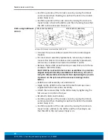
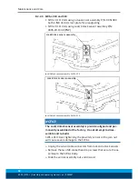
8.2.2.4 SWS-L-1210
Lock Sensor
Assembly
(3 Places)
Unlock
Sensor
Assembly
(3 Places)
Lock and Unlock Sensor Assemblies SWS-L-1210
NOTICE
The Lock and Unlock sensor assemblies are precision aligned and per-
manently assembled at the factory. Do not attempt to adjust the po-
sition of the sensor or severe damage to the SWK-L may occur.
Ø
Unscrew the sensor cable connector from the extension cable.
Ø
Remove the two M3 socket head cap screws that secure the as-
sembly to the SWK-L body.
Ø
Slide the sensor assembly out and discard.
Ø
Apply Loctite 222MS to the new M3 socket head cap screws
supplied with the new sensor assembly.
Ø
Check that the new sensor assembly has the o-ring present and
that the old oring came off of the SWK-L with the old sensor as-
sembly. Attach the new assembly to the SWK-L by tightening
the M3 screws to 1.36 Nm.
Ø
Re-attach cables and modules.
Ø
Confirm operation of the Unlock sensor by issuing the Unlatch
command and then checking to see that the LED in the Unlock
sensor body is on.


