Maintenance and Care
54
02.00 | SWS-L | Assembly and operating manual | en | 0389037
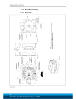
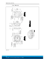
8.4.2 SWS-L-310
244
Square
SWK-L &
SWA-L
See Note 1
Flat A
Ø 12 (Slip Fit)
18 Dp.
Customer Interface
45°
Flat B
B.C. Ø200
Flat C
(10) C'Bored 14.5 Dp.
From Far Side
for M12 SHCS
30° Spacing-Skip Ø 12 Dowel
& Location Opposite
Customer Interface
15°
(12) C'Bored 16.4 Dp.
From Far Side
for M16 SHCS
Equally Spaced
Customer Interface
Flat D
[4.72"]
120
Coupled
47.2
Pin
68.1
SWK-L
52.1
SWA-L
See Note 4
(A)
(B)
Flat B
(2) Ø 12 (Slip Fit)
18 Dp.
Equally Spaced
Customer interface
45°
(6) Tapped M16x2.0
See Table 1 for Thread Depth
Equally Spaced
Customer Interface
Flat A
Tool Cover
B.C Ø200
B.C. Ø 160
Ø125 H7, 5 Dp.
(See Note 3)
Customer Interface
Flat D
(2) Ø10 (Slip Fit)
16 Dp.
Equally Spaced
Customer Interface
45°
Flat C
(10) Tapped M10x1.5, 19 Dp.
30° Spacing
Skip Ø10 Dowels
Customer Interface
(10) Tapped M12x1.75, 20 Dp.
30° Spacing
Skip Ø 12 Dowels
Customer Interface
(Optional Bolt Down Note 2)
30°
Typ.
15°
Scale 1:4
Part Numbers:
(A) SWK-L: 9121-310AMX-0-0-0-0
(B) SWA-L: 9121-310DT-0-0-0-0
Notes:
1) Center Boss inserts available
2) Optional Bolt Down: (10) Holes C'Bored from opposite side 10.2 deep for M10 SHCS.
3) Tool cover must be removed to utilize this customer interface feature.
4) Remove plug if necessary to avoid interface with customer tooling.
Assembly drawing SWS-L 310

