Maintenance and Care
58
02.00 | SWS-L | Assembly and operating manual | en | 0389037
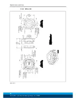
8.4.4 SWS-L-1210
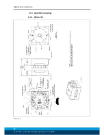
(4) C'Bored 10.4 Dp.
From Far Side
For M10 SHCS
Customer Interface
137.2
30°
87.6
15°
(2) R113.5
(2) C'Bored 10.4 Dp.
From Far Side
For M10 SHCS
Customer Interface
250
158.4
28°
14°
(10) C'Bored 10.6 Dp.
From Far Side
For M10 SHCS
30° Typ. Spacing
Pattern (3) Places
Customer Interface
B.C. Ø125
(3) Places
Customer Interface
45.7
15°
(2) Ø12(Slip Fit)
13.5 Dp.
Customer Interface
30°
(4)R115.5
(A)
68.1
SWK-L
[4.81"]
122.2
Coupled
54.1
SWA-L
(B)
Slide View
(Uncoupled)
SWK-L Side
(projection only)
81.3
(35.6)
B.C Ø91
(3) Places
Customer Interface
(12) C'Bored 41.9 Dp.
From Far Side
For M10 SHCS
Equally Spaced
Pattern (3) Places
Customer Interface
15.8.4
SWA-L Side
(projection only)
Ø359
SWK-L & SWA-L
87.6
137.2
305
SWK-L & SWA-L
123.2
351
SWK-L & SWA-L
Part Numbers:
(A) SWK-L: 9121-1210AM-0-0-0-0-0-0
(B) SWA-L: 9121-1210AT-0-0-0-0-0-0
Flat B
Flat C
Flat D
Flat A
Flat F
Flat E
Flat D
Flat A
Flat C
Flat B
Notes:
1. Tool Changer consists of three locking mechanisms and share a common lock
and unlock air supply.
2. Tool Changer capable of detecting 'Lock' and 'Unlock' for each locking mechanism.
3. Tool Changer capable of detecting 'RTL' (Ready-to-Lock) using (3) proximity sensors.
SWS-L 1210


